
Method for measuring intensity of interference signal based on csi-rs in wireless communication system and apparatus for same

a wireless communication system and intensity measurement technology, applied in the field of wireless communication system, can solve problems such as the extended range of inter-cell interferen

Active Publication Date: 2015-01-15
LG ELECTRONICS INC
View PDF3 Cites 5 Cited by
  • Summary
  • Abstract
  • Description
  • Claims
  • Application Information

AI Technical Summary

Benefits of technology

The patent allows a user equipment to measure the strength of interference signals in a wireless communication system using a CSI-RS. This is useful in various situations and improves the efficiency of the communication.

Problems solved by technology

Moreover, since CoMP has various transmission schemes, the extent of inter-cell interference varies according to the various transmission schemes.

Method used


Image

  • Method for measuring intensity of interference signal based on csi-rs in wireless communication system and apparatus for same
  • Method for measuring intensity of interference signal based on csi-rs in wireless communication system and apparatus for same
  • Method for measuring intensity of interference signal based on csi-rs in wireless communication system and apparatus for same

Examples


Embodiment Construction

[0037]In the following description, compositions of the present invention, effects and other characteristics of the present invention can be easily understood by the embodiments of the present invention explained with reference to the accompanying drawings. Embodiments explained in the following description are examples of the technological features of the present invention applied to 3GPP system.

[0038]In this specification, the embodiments of the present invention are explained using an LTE system and an LTE-A system, which is exemplary only. The embodiments of the present invention are applicable to various communication systems corresponding to the above mentioned definition. In particular, although the embodiments of the present invention are described in the present specification on the basis of FDD, this is exemplary only. The embodiments of the present invention can be applied to H-FDD or TDD in a manner of being easily modified.

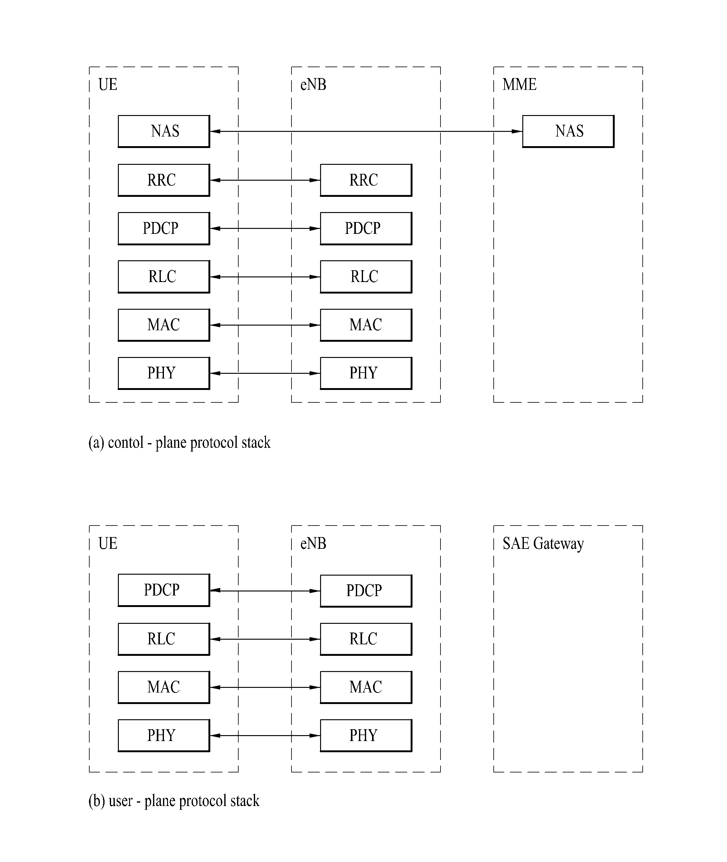
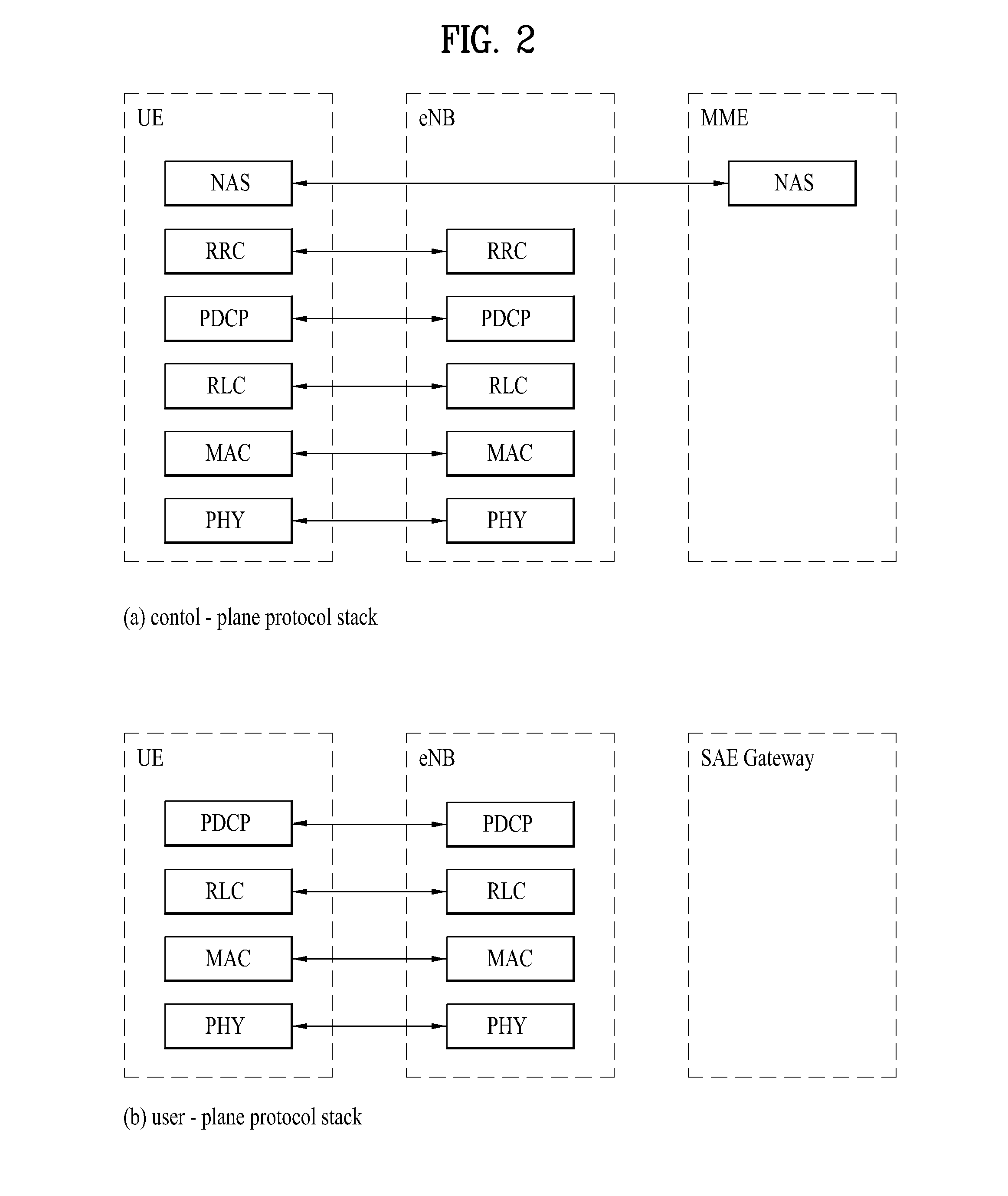
[0039]FIG. 2 is a diagram for structures of con...


PUM


Abstract

Disclosed is a method for measuring the intensity of an interference signal by a terminal in a wireless communication system. More particularly, a method for measuring the intensity of an interference signal from a first base station by a terminal in a coordinated multipoint (CoMP) environment comprises: a step of receiving a plurality of channel status information-reference signals (CSI-RSs) from a second base station; a step of receiving downlink signals output from a plurality of resource element (RE) pairs corresponding to the respective plurality of CSI-RSs from the first base station; and a step of measuring a plurality of interference intensities based on the plurality of CSI-RSs and the received downlink signals.

Description

TECHNICAL FIELD[0001]The present invention relates to a wireless communication system, and more particularly, to a method of measuring strength of an interference signal based on a CSI-RS (channel status information-reference signal) in a wireless communication system and an apparatus therefor.BACKGROUND ART[0002]3GPP LTE (3rd generation partnership project long term evolution hereinafter abbreviated LTE) communication system is schematically explained as an example of a wireless communication system to which the present invention is applicable.[0003]FIG. 1 is a schematic diagram of E-UMTS network structure as one example of a wireless communication system. E-UMTS (evolved universal mobile telecommunications system) is a system evolved from a conventional UMTS (universal mobile telecommunications system). Currently, basic standardization works for the E-UMTS are in progress by 3GPP. E-UMTS is called LTE system in general. Detailed contents for the technical specifications of UMTS an...

Claims


Application Information

Patent Timeline
Patent Type & Authority Applications(United States)
IPC IPC(8): H04W24/08H04L5/00
CPCH04L5/0048H04W24/08H04B17/345H04B7/024H04B7/0632H04B7/0684H04B1/1027H04L1/0026H04L5/0023H04L5/0035
Inventor KIM, HYUNGTAEPARK, JONGHYUNKIM, KIJUN
Owner LG ELECTRONICS INC
Learn More