
Strength measuring method of honeycomb structure having insertion hole

a honeycomb structure and strength measurement technology, which is applied in the direction of instruments, lighting and heating apparatus, ceramicware, etc., can solve the problems of inability to directly measure the concentration of harmful substances in exhaust gas using a sensor, heat is usually taken, and the sensor function might be lost, so as to reduce the load around the insertion hole, the strength of the honeycomb structure provided with the insertion hole can be measured, and the degree of the strength of the honeycomb structure is reduced

Active Publication Date: 2010-05-11
NGK INSULATORS LTD
View PDF7 Cites 0 Cited by
  • Summary
  • Abstract
  • Description
  • Claims
  • Application Information

AI Technical Summary

Benefits of technology

This method allows for accurate measurement of the honeycomb structure's strength without cracking the hole edges, ensuring the structure can endure the loads imposed during sensor installation and use, thus maintaining sensor functionality and accuracy.

Problems solved by technology

However, in a case where it is confirmed whether or not the harmful substances have actually been decreased, it is difficult to directly measure the concentration of the harmful substances in the exhaust gas by use of a sensor.
Moreover, heat is usually taken by vaporization of the condensate water to disturb the early heating of the sensors.
When the honeycomb structure is broken, a sensor function might be lost, and a detection accuracy might lower.
However, when the strength of the honeycomb structure provided with the holes is measured by an isostatic breakdown strength test, there are confronted problems that hole edge portions are cracked by urethane wrapping the honeycomb structure therein or urethane is broken and that the strength of the honeycomb structure cannot be measured.

Method used


Image

  • Strength measuring method of honeycomb structure having insertion hole
  • Strength measuring method of honeycomb structure having insertion hole
  • Strength measuring method of honeycomb structure having insertion hole

Examples


example 1

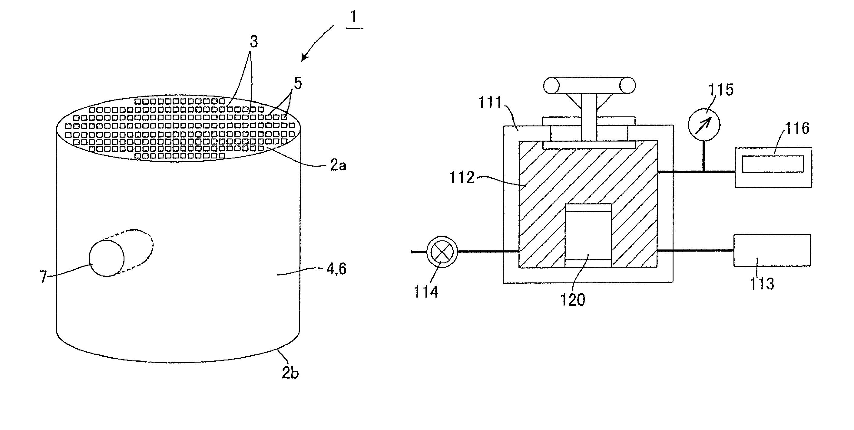
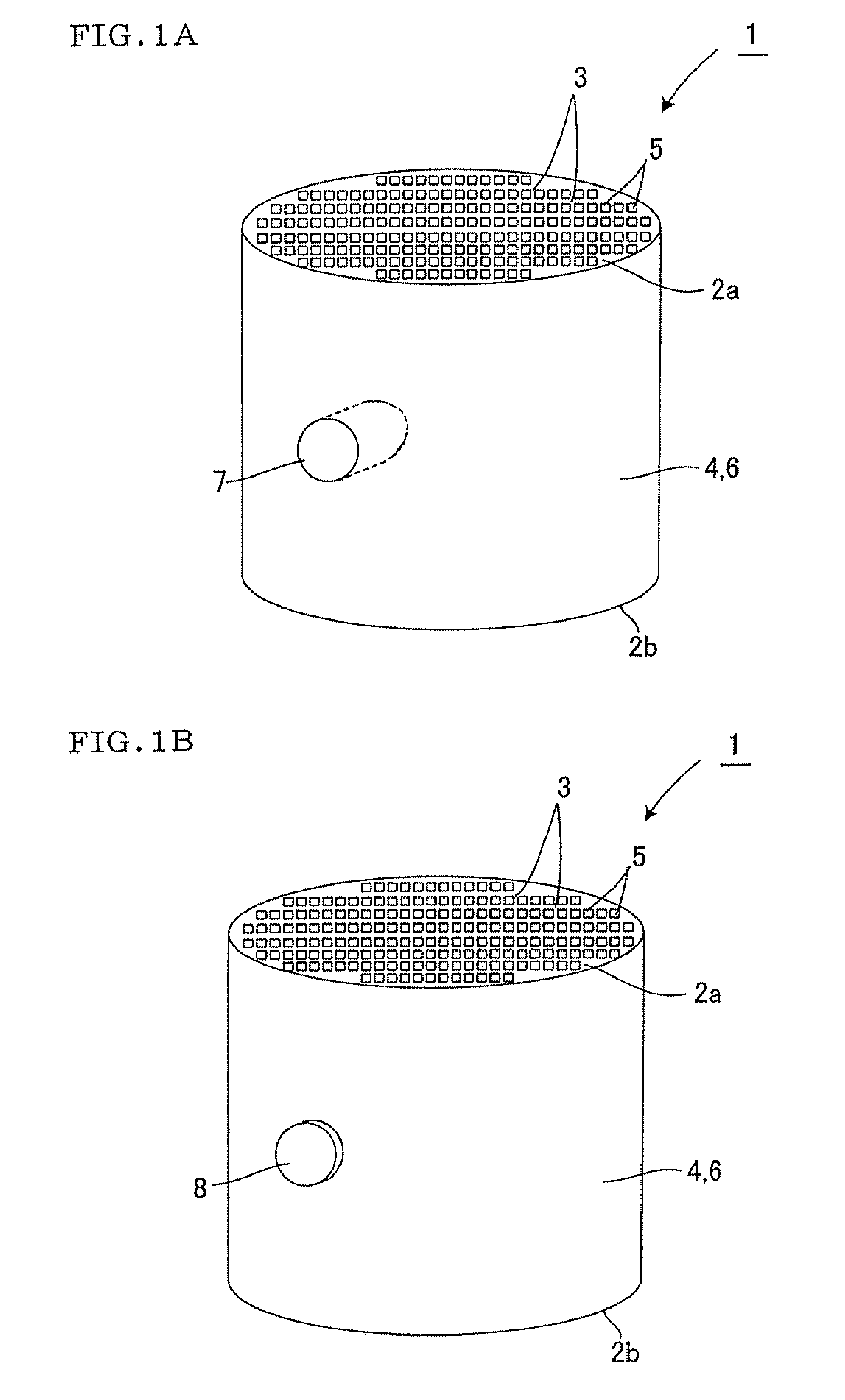
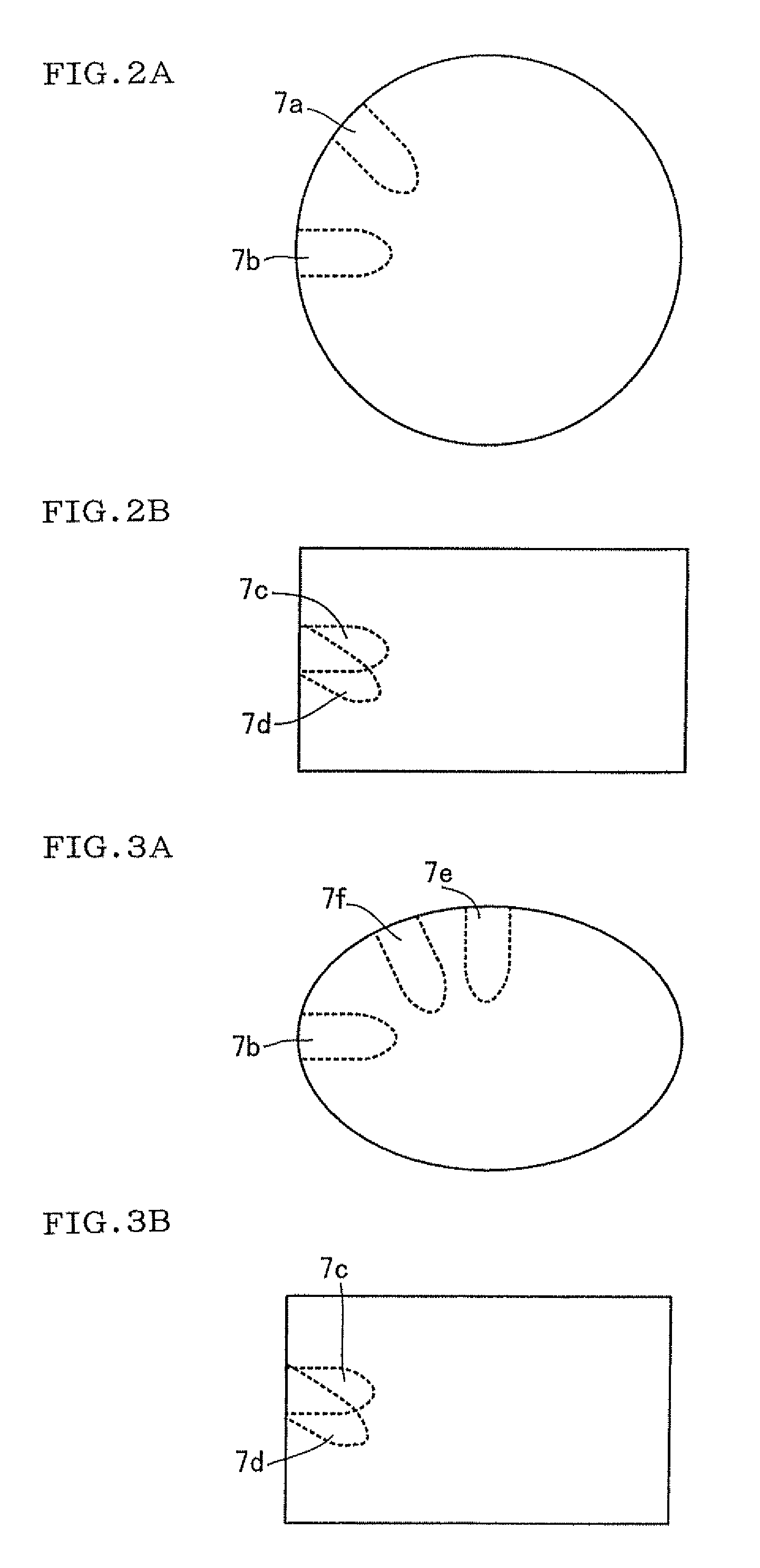
[0064][Preparation of Honeycomb Structure] As a raw material, a cordierite forming material including talc, kaolin and alumina as main materials is blended with water, a binder, a surfactant or the like, and the resultant mixed and kneaded forming material was extrusion-formed using a clay kneader and an extruder to obtain a formed honeycomb article having partition walls which separate and form a plurality of cells constituting fluid flow paths and an outer wall formed integrally with the partition walls. Then, the resultant formed honeycomb article was dried, then cut into predetermined lengths, and fired to obtain a honeycomb structure. As to the size and the shape of the resultant honeycomb structure, the structure had a columnar shape with a diameter of 118.4 mm and a total length (the length of the central axis) of 152.4 mm (see the shape shown in FIGS. 2A and 2B), the thicknesses of the partition walls were 0.15 mm (6 mil), a cell density was about 62 cells / cm2 (400 cells / squ...

examples 2 to 20

, Comparative Examples 1 to 35, and Reference Examples 1 and 2

[0069]The hardness of each rubber plug was changed, and the size of the rubber plug was changed to change a clearance and a protruding height, respectively. Except this respect, in the same manner as in Example 1, each honeycomb structure was prepared and provided with an insertion hole, and the structure including the rubber plug inserted into the hole was subjected to a strength test. The result of evaluation is shown in Tables 1, 2 and 3 together with a drawing number showing the type of the rubber plug, the hardness of the rubber plug, the clearance and the protruding height.

[0070]It is to be noted that in Examples 1 to 10 and Comparative Examples 1 to 9, when the rubber plug had a hardness of 65 and the structure had the same conditions other than the hardness, the same result as that in a case where the plug had a hardness of 45 was obtained. Moreover, when the conditions other than the hardness in Examples 11 to 20...

example 21

[0073]As a rubber plug, a rubber plug having a shape shown in FIG. 7 and a hardness of 70 was used. FIG. 7 is a sectional view showing the shape of a used rubber plug 8b and corresponding to a diagram of the insertion hole 7 shown in FIG. 5. The shape of the used rubber plug 8b was substantially the same as that of the insertion hole 7, so that the only bottom surface thereof was semispherical and another portion was substantially columnar. A top surface portion (an upper surface portion, i.e., an exposed portion of the inserted rubber plug on the side of the peripheral surface of a honeycomb structure) is recessed in a pot-bottom-like shape. Except this respect, in the same manner as in Example 1, the honeycomb structure was prepared and provided with an insertion hole, and the structure including the rubber plug inserted into the hole was subjected to a strength test. The result of evaluation is shown in Table 4 together with a drawing number showing the type of the rubber plug, t...


PUM

PropertyMeasurementUnit
depthaaaaaaaaaa
depthaaaaaaaaaa
heightaaaaaaaaaa

Abstract

There is disclosed a method for measuring the strength of a honeycomb structure provided with an insertion hole preferably without generating any chipping. In the strength measuring method of the honeycomb structure, the strength is measured while a rubber plug is inserted into the insertion hole. The rubber plug has a hardness of 45 or more and 90 or less, a clearance between the inserted rubber plug and the inner surface of the insertion hole parallel to the depth direction of the insertion hole is 0.2 mm or more and 2.6 mm or less, and the protruding height of the inserted rubber plug from the peripheral surface of the honeycomb structure is 0.5 mm or more and 5 mm or less.

Description

BACKGROUND OF THE INVENTION[0001]1. Field of the Invention[0002]The present invention relates to a method for measuring the strength of a honeycomb structure provided with a hole into which, for example, a sensor is inserted.[0003]2. Description of the Related Art[0004]To prevent environmental pollution and improve the environment, a catalyst converter is used for the treatment of an exhaust gas from a car. This catalyst converter converts harmful substances (nitrogen oxide, carbon monoxide, etc.) included in the exhaust gas into components which can be discharged to the environment in accordance with law's provisions. When the exhaust gas passes through the catalyst converter, the harmful substances included in the gas are decreased.[0005]However, in a case where it is confirmed whether or not the harmful substances have actually been decreased, it is difficult to directly measure the concentration of the harmful substances in the exhaust gas by use of a sensor.[0006]To solve the p...

Claims


Application Information

Patent Timeline
Patent Type & Authority Patents(United States)
IPC IPC(8): G01N19/08G01N3/08
CPCC04B35/195C04B38/0006G01N3/12F01N13/008C04B38/0054C04B38/0074C04B2111/00793C04B2235/3217C04B2235/3445C04B2235/349F23J2219/10
Inventor TOYOSHIMA, HIDEYUKIKONDO, TAKAHIRO
Owner NGK INSULATORS LTD
Learn More