Pump head for a fuel pump

a technology for pump head and fuel pump, which is applied in the direction of liquid fuel engine, machine/engine, positive displacement liquid engine, etc., can solve the problems of affecting the efficiency of the pump head, so as to reduce or prevent the leakage of fuel and correct the positioning of the sleeve

Inactive Publication Date: 2015-01-15
DELPHI INT OPERATIONS LUXEMBOURG S A R L
View PDF5 Cites 6 Cited by
  • Summary
  • Abstract
  • Description
  • Claims
  • Application Information

AI Technical Summary

Benefits of technology

[0022]The sleeve may comprise a sealing member disposed adjacent to an end face of the turret portion for receiving the pumping element therethrough, to reduce or prevent leakage of fuel that escapes from the turret portion. In an advantageous arrangement, the sealing member is spaced from the end face of the turret portion to define a radial flow path therebetween allowing flow from the plunger bore to the leakage flow path. The radial flow path may be provided instead of or in addition to one or more through-bores in the turret portion.
[0023]The sleeve preferably co...

Problems solved by technology

Because fuel in the pumping chamber reaches very high pressures, the pump head can be subjected to relatively high, cyclical stresses in use.
In such cases, undesirable contamination of the engine oil can occur if fuel...

Method used


Image

  • Pump head for a fuel pump
  • Pump head for a fuel pump
  • Pump head for a fuel pump

Examples


second embodiment

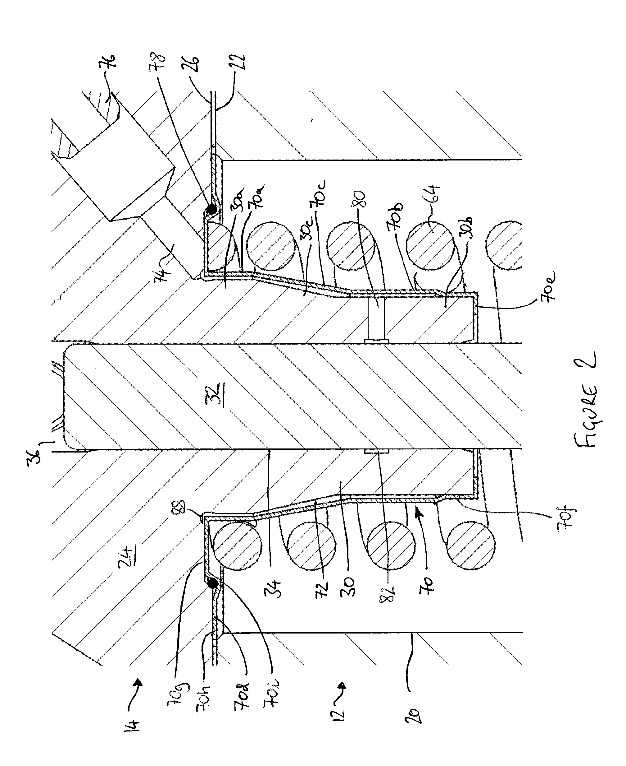
[0057]In the invention, the distal tubular region 70d of the sleeve 70 is extended beyond the end of the turret portion 30 of the pump head 14, so that the inwardly-directed flange region 70e is spaced from the end of the turret portion 30. An annular seal member 84 is disposed around the plunger and is retained in the space between the end of the turret portion 30 and the inwardly-directed flange region 70e. A gap 86 between the seal member 84 and the end of the turret portion 30 allows fuel to flow in a radial direction from the end of the plunger bore 34 into the annular space 72, thereby supplementing the flow through the through-drilling 80, and decreasing further the amount of fuel that leaks from the plunger bore 34 into the port 20.

[0058]Unlike in the first embodiment of the invention, in this second embodiment the distal tubular region 70b of the sleeve 70 does not include a reduced-diameter portion at its lower end, since this would block the flow of fuel from the gap 86 i...

third embodiment

[0061]In this third embodiment, the collection groove and the through-bore are omitted, and instead the plunger bore 34 communicates with the annular space 72 defined by the sleeve 70 only by way of the gap 86 between the seal member 84 and the end of the turret portion 30. In this embodiment, because the distance between the pumping chamber 36 and the gap 86 is maximised, the quantity of pressurised fuel that escapes from the pump head 14 through the leakage return passage 74 is minimised.

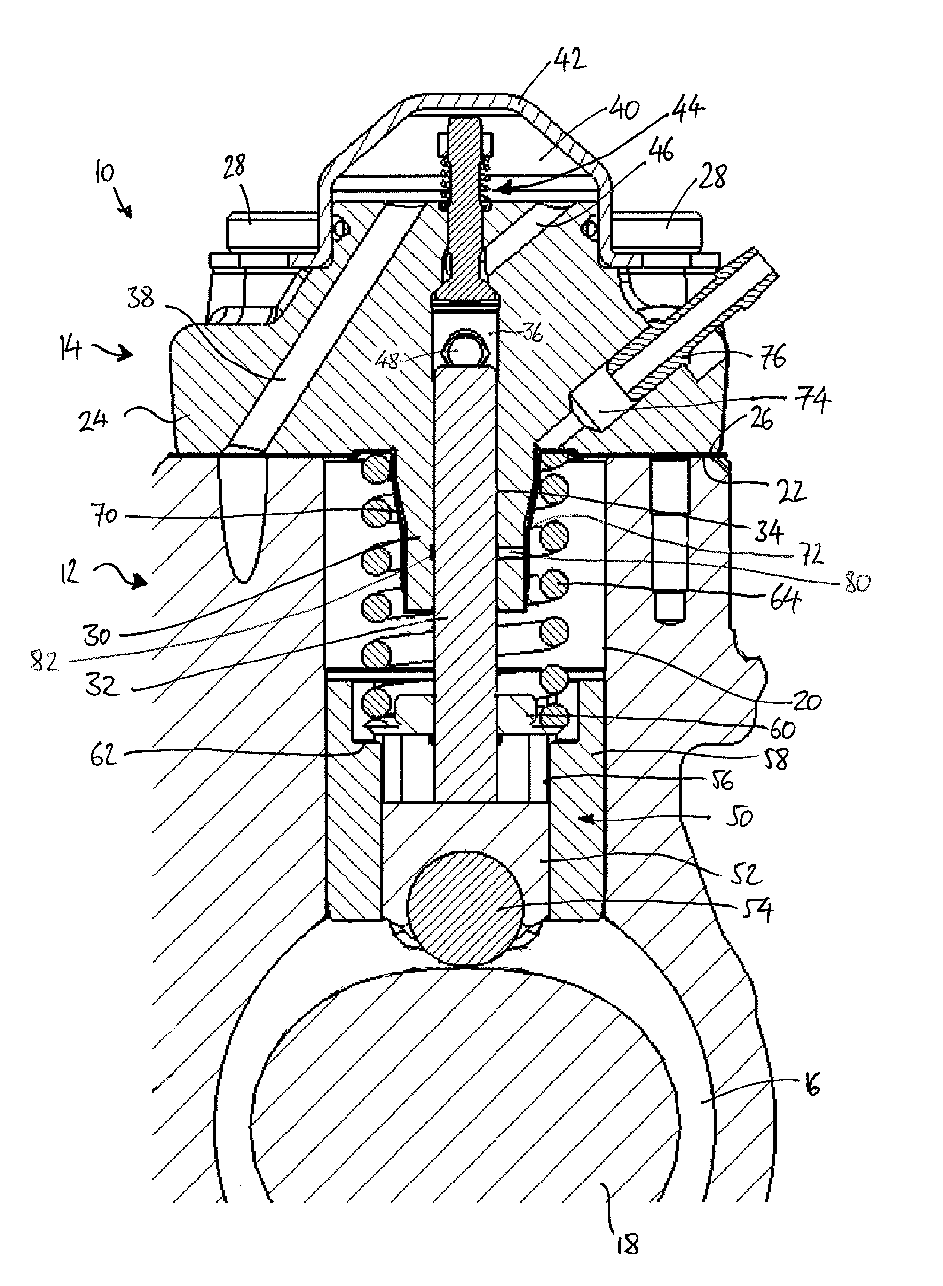
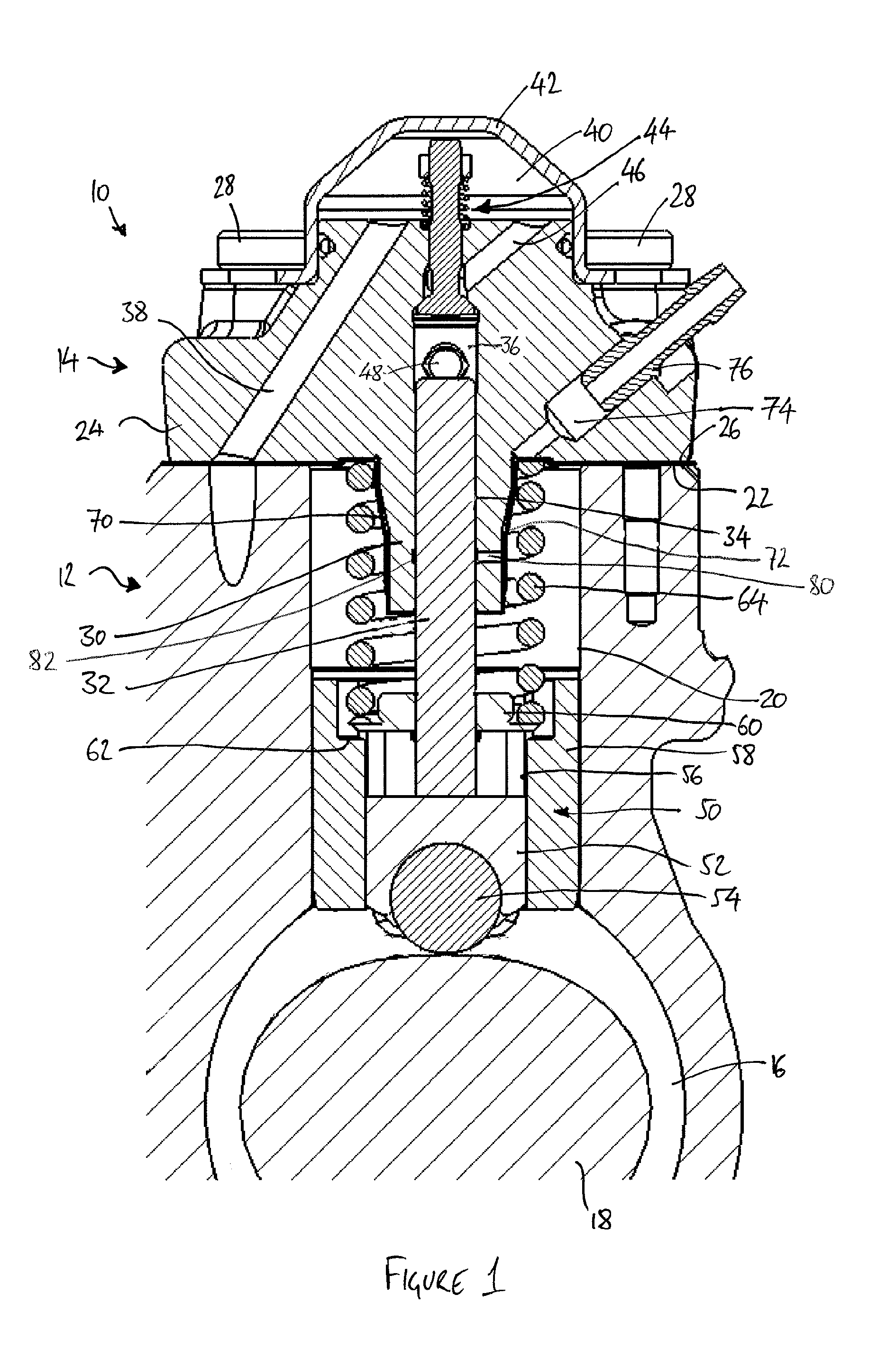
[0062]In each of the described embodiments, the design of the pump head 14 is adapted to minimise stress concentrations within the pump head 14 in order to maximise its strength and avoid fatigue damage under the cyclical pumping loads. For example, the turret portion 30 meets the body portion 24 of the pump head 14 at a radiused groove 88, so as to avoid the presence of a sharp corner at this point.

[0063]The arrangement of the leakage return passage 74 at approximately 45° to the axis of the plun...


PUM


Abstract

A pump head for a high-pressure fuel pump is disclosed. The pump head comprises a head housing including a body portion, and a turret portion extending from the body portion, a pumping chamber defined within the body portion, a pumping element bore for receiving a pumping element in use, the pumping element bore extending from the pumping chamber and through the turret portion, and a leakage return passage. The pump head further comprises a sleeve arranged around the turret portion to define a leakage flow path to allow fuel flow from the pumping element bore to the leakage return passage. The pump head is suitable for use in a fuel pump of the type in which a cam drive arrangement of the pump is lubricated by engine oil, since contamination of the engine oil with fuel can be minimised.

Description

CROSS REFERENCE TO RELATED APPLICATIONS[0001]This application is a national stage application under 35 U.S.C. 371 of PCT Application No. PCT / EP2013 / 051674 having an international filing date of 29 Jan. 2013, which designated the United States, which PCT application claimed the benefit of European Patent Application No. 12153101.6 filed 30 Jan. 2012, the entire disclosure of each of which are hereby incorporated herein by reference.FIELD OF THE INVENTION[0002]The present invention relates to a pump head for a pump. In particular, but not exclusively, the present invention relates to a pump head for a high-pressure fuel pump assembly of the type in which the fuel to be pumped is separated from the drive mechanism of the fuel pump assembly.BACKGROUND TO THE INVENTION[0003]In modern common-rail fuel injection systems, and particularly in diesel fuel injection systems, it is desirable to supply fuel to the fuel injectors at very high pressures.[0004]One known type of fuel pump assembly s...

Claims


Application Information

Patent Timeline
IPC IPC(8): F02M21/02
CPCF02M21/0245F02M59/102F04B1/0421F04B1/0439F04B1/0448F02M59/442F04B53/162F02M59/06F02M59/10F02M59/44F04B1/04
Inventor MCCRINDLE, CHRISTOPHER
Owner DELPHI INT OPERATIONS LUXEMBOURG S A R L
Why Eureka
Try Eureka