Bi-component fiber for the production of spunbonded fabric

Inactive Publication Date: 2015-01-15
EWALD DORKEN
View PDF3 Cites 5 Cited by
  • Summary
  • Abstract
  • Description
  • Claims
  • Application Information

AI Technical Summary

Benefits of technology

[0012]The positive influence of the advantageous differences between the MFIs essentially relates to the specific tearing force and the specific nail tear resistance. These two characteristic values of a spunbond fabric produced from the fibers can be improved by the advantageously selected MFIs. In this case, even a simultaneous increase of both characteristic values is possible, but in any case, one of the two characteristic values can be improved without the other characteristic value deteriorating. This also has a positive effect on the haptic properties. Thus, the specific tearing force can be increased without softness and the so-called “textile grip” being negatively influenced. In this case, textile grip is defined as a pleasant feeling upon contact.
[0013]In connection with the invention, it is advantageous when the difference between the MFIs of the first component and the second component is less than or equal to 20 g/10 minutes, preferably 15 g/10 minutes, and/or the MFIs of the first component and the second component in each case are less than or equal to 40 g/10 minutes. It is pointed out that any individual intervals or individual values are contained in the indicated intervals and are to be considered disclosed as essential to the invention, even if they are not mentioned in detail. In these advantageous parameter ranges, the positive effects of this invention come significantly strongly to the fore.
[0014]The positive effects of this invention also include the fact that

Problems solved by technology

In practice, however, the use of these synergistic effects is limited to the extent that the properties of the components cannot routinely be combined in the described, only advantageous way.
Another problem that arises in the case of bi-component fibers is the limited recyclability of the bi-com

Method used


Image

  • Bi-component fiber for the production of spunbonded fabric
  • Bi-component fiber for the production of spunbonded fabric
  • Bi-component fiber for the production of spunbonded fabric

Examples


Example

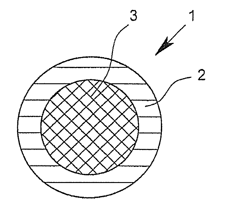
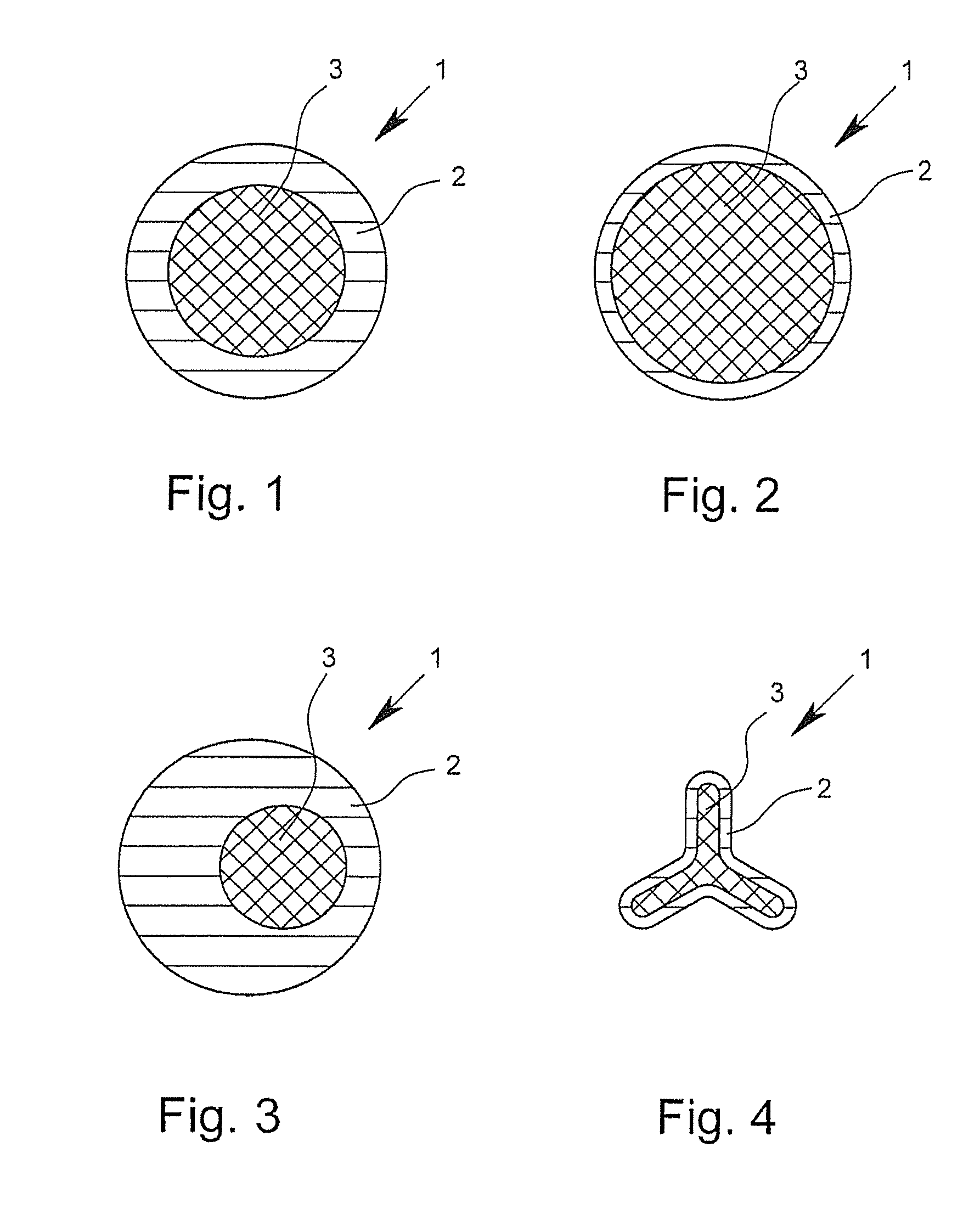
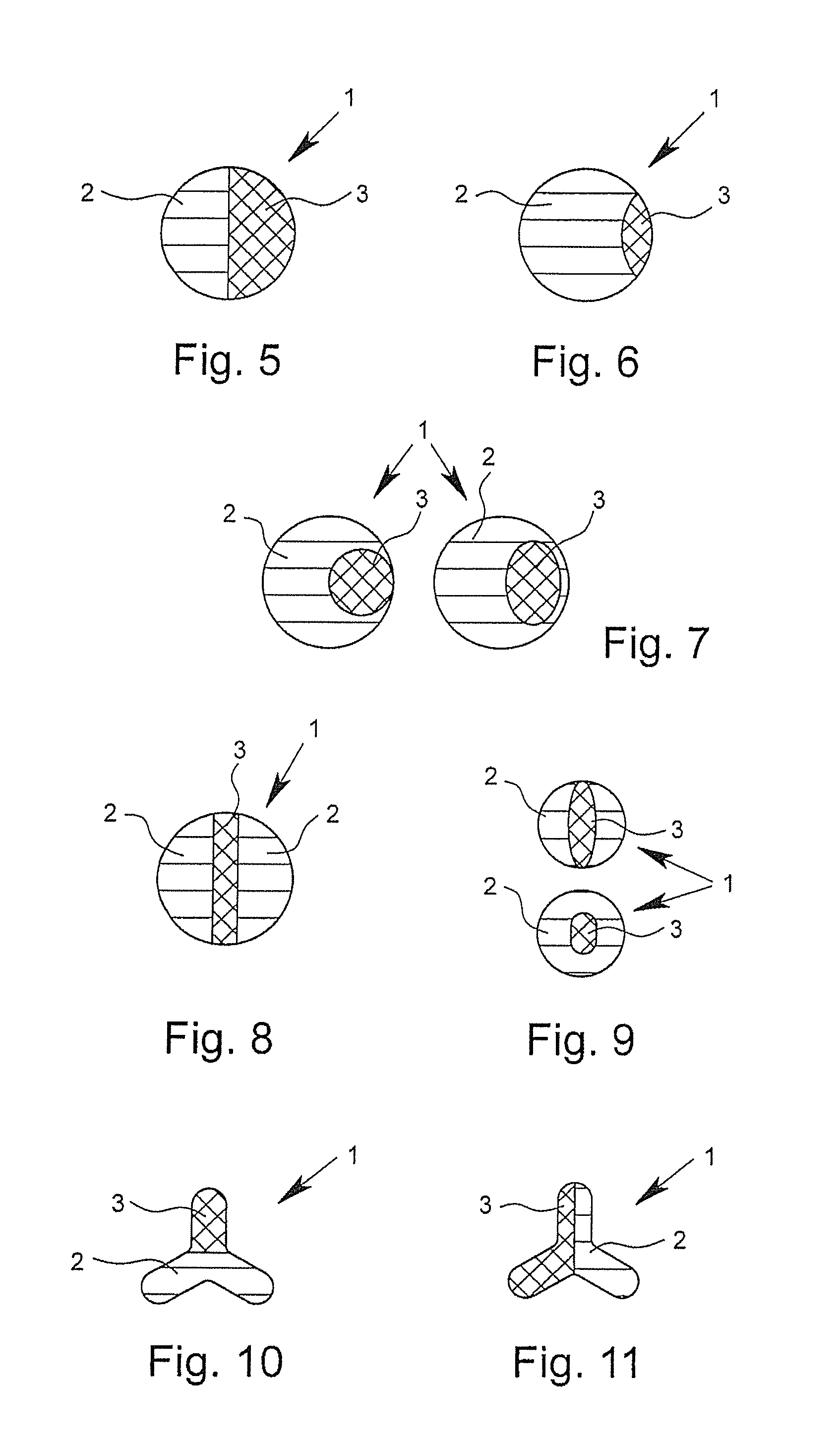
[0096]FIGS. 1 to 16 show cross-sectional views of bi-component fibers 1 according to the invention by way of example. The depicted bi-component fibers 1, in each case, have a first component 2 and a second component 3. In the core-sheath fibers depicted in FIGS. 1 and 4, in this case, the first component 2 surrounds the second component 3 and thus forms the outer surface of the fiber. In this case, the bi-component fibers 1 depicted in FIGS. 1 to 3 have an at least approximately circular or round geometry in cross-section. The bi-component fiber depicted in FIG. 4 shows, however, a trilobal cross-section. Such trilobal cross-sections, like other multilobal cross-sections as well, have the effect that the fiber has a larger outer surface in relation to its mass than is the case with fibers with a circular cross section. In the case of “core-sheath fibers,” in which the proportion of the components forming the sheath is very small, for example approximately 2%, but certainly even in “...


PUM

PropertyMeasurementUnit
Fractionaaaaaaaaaa
Fractionaaaaaaaaaa
Fractionaaaaaaaaaa

Abstract

A bi-component fiber (1), in particular for the production of spunbond fabrics (4), with a first component (2) and a second component (3), whereby the first component (2) has a first polymer as an integral part and the second component has a second polymer as an integral part. It is provided that the difference between the melt-flow indices of the first component (2) and the second component (3) is less than or equal to 25 g/10 minutes and that the melt-flow indices of the first component (2) and the second component (3) in each case are less than or equal to 50 g/10 minutes.

Description

BACKGROUND OF THE INVENTION[0001]1. Field of the Invention[0002]The invention relates to a bi-component fiber, in particular for the production of spunbond fabric, with a first component and a second component, whereby as integral parts, the first component has a first polymer and the second component has a second polymer. In addition, the invention relates to a spunbond fabric with at least one bi-component fiber of the above-mentioned type.[0003]2. Description of Related Art[0004]Bi-component fibers of the type in question usually have a first component that consists of a first polymer and a second component that consists of a second polymer. In this case, different types of bi-component fibers can be distinguished, which in each case have different characteristic distributions of the components in the fiber cross-section. Bi-component fibers, in which the first component surrounds and thus encompasses the second component in the cross-section of the fiber, are referred to as core...

Claims


Application Information

Patent Timeline
IPC IPC(8): D01F8/06D04H1/541D01F8/18
CPCD01F8/06D04H1/541D01F8/18Y10T428/2929D04H3/005D04H3/147Y10T442/637D04H1/5412D04H1/5416D04H1/5414
Inventor SCHROER, JORNPLACKE, DANIEL
Owner EWALD DORKEN
Why Eureka
Try Eureka