Light redirection device

a technology of redirecting devices and light sources, which is applied in the direction of lighting and heating apparatus, instruments, and using daylight, etc., can solve the problems of glare, insufficient amount of light that is transmitted into the room, and often too small light amount to be sufficient,

Active Publication Date: 2015-01-22
SIGNIFY HLDG BV
View PDF7 Cites 4 Cited by
  • Summary
  • Abstract
  • Description
  • Claims
  • Application Information

AI Technical Summary

Benefits of technology

[0009]By providing the redirection device with four occurrences of refraction, i.e. two for each way it passes through the transparent element, and one reflection in the reflecting element, incident light is deviated a lot from the incident angle making it possible to make a horizontal planar device and direct incident vertical daylight into an almost horizontal direction. The redirected light is also focused in that the redirected light has a smaller cross section area than the incident light and the top area of the redirection device, The arrangement also makes the output angle of light very insensitive to the incident angel variation of the sun during the day. When for example having the device at the upper part of a window as a shading plate, incident light can be redirected towards the ceiling of the room inside the window illuminating in substantially the same way all day, despite variations in the angle of incident light due to sun movement. The device is also possible to make very thin, since the transparent elements and the light reflectors can be made small and in great numbers in rows. In the horizontal direction of the window surface, the transparent elements and light reflectors, respectively, may be as long as the redirecting device. Since the transparent elements and light reflectors are placed in rows it is understood that incident light that is transported through one transparent element and reflected in a light reflector, may be transported through a transparent element in the next row.
[0011]Daylight collection and transport can be performed via total internal reflection (TIR) in optical transparent media or via specular reflective metal surfaces as proposed in the device of the current invention. Reflective surfaces benefit over TIR as they transport a substantially larger part of the diffuse light, as daylight. In addition, due to its nearly flat spectral absorption the colour temperature of the transported light remains very close to that of daylight and as a result increases the impression of connectivity.
[0026]The planar surfaces of the transparent surfaces and the light reflector may also be made slightly curved or randomly distorted to reduce glare when the light direction device is used for illumination of a ceiling directly inside a window.

Problems solved by technology

Daylight may, however, also lead to uncomfort due to glare.
A problem is then that the amount of light that is transmitted into the room often is too small to be sufficient and electrical lighting has to be used as compensation.
In strong sunlight this solution, however, still produces too much glare.
A scattering surface also reduces the transparency ofthe window so that it is useless for viewing through.
Using prisms also reduce or destroy the ability to see through the window, affecting the function of the window to view through.
Another problem using prisms inside the window is that the illumination of the ceiling will change as the sun angle shifts during the day if not active movement of the prisms is achieved to follow the sun movements.
The collection systems are, however, bulky and not favourable from an esthetical point of view, leading to a resistance to them from architects.
The bulky construction may also be in the way of other equipment wanted on the building.

Method used


Image

  • Light redirection device
  • Light redirection device
  • Light redirection device

Examples


Embodiment Construction

[0034]In the various Figs. of the drawing identical parts are always given the same reference number so that they are generally only described once in the detailed description below.

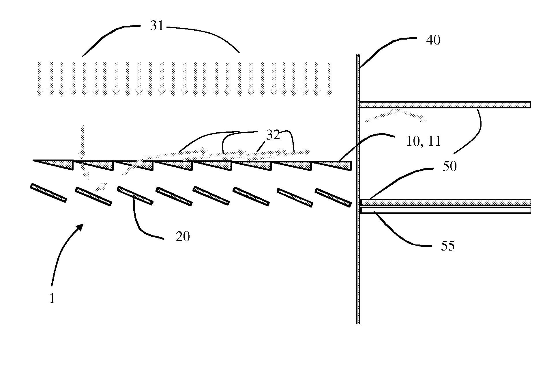
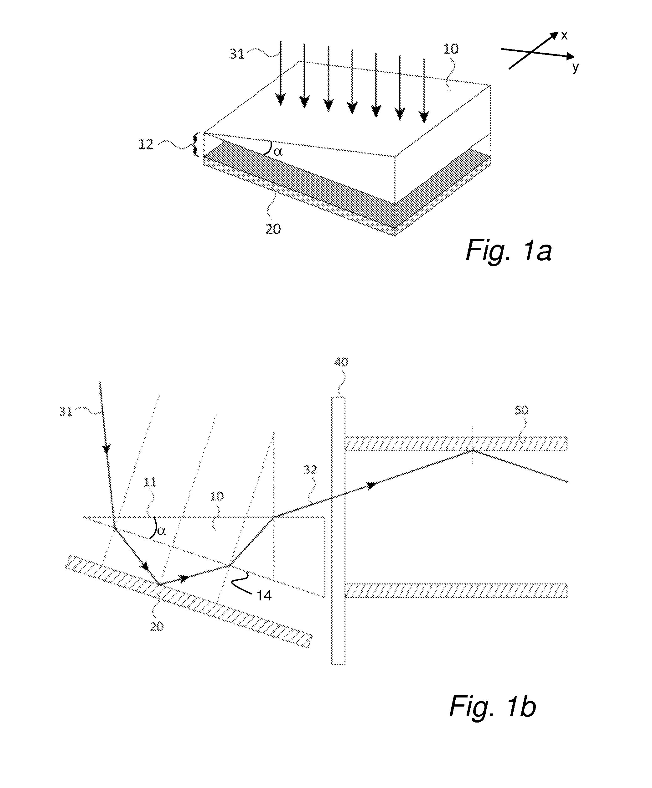
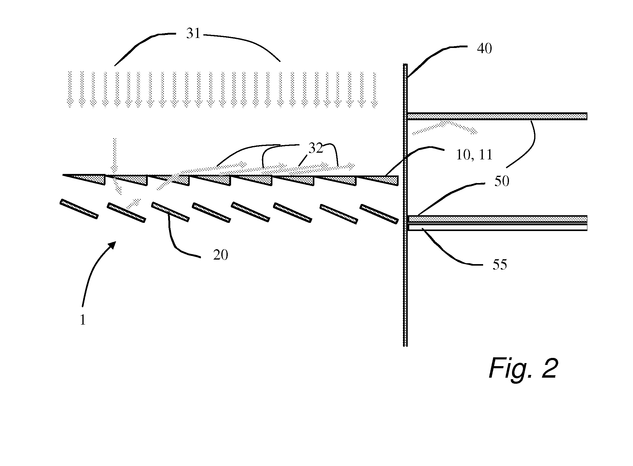
[0035]FIG. 1a and FIG. 1b shows the principle of the device according to the invention having one transparent element 10 and one light reflector 20. The light reflector 20 is arranged at a side of the triangular prism or transparent element 10 opposite from a light receiving side 11. The triangular prism has an angle α between its top (11) and bottom (14) surfaces. The reflective element 20 is parallel to the bottom surface of the prism.

[0036]The light reflector 20 may be in optical contact with the triangular prism 10, but is preferably spaced a certain distance 12 away from the triangular prism 10 to achieve an additional refraction. When collimated light 31 is incident on the light receiving side 11 of the triangular prism 10, it is first refracted towards the light reflector 20, reflected back into t...


PUM


Abstract

The present invention relates to a light redirection device (1) for redirecting and concentrating direct sunlight (31) into buildings, said device comprising at least one transparent element (10) having a substantially planar top surface (10) in an x-y-plane and a substantially planar bottom surface (14), wherein said top (11) and bottom (14) surfaces are arranged in an angle α to each other around the x-axis, and a light reflector (20) for each transparent element (10) having a planar surface, wherein said planar surface of said light reflector (20) is arranged substantially parallel and adjacent said bottom surface (14) of said transparent element (10), wherein said reflective surface is spaced apart (12) from said transparent element by a transparent medium having lower refractive index than the transparent element (10), so that incident light (31) to the device is refracted by each material transition interface and reflected by the reflecting element (20). The invention further relates to a method for redirecting and concentrating direct sunlight (31) into buildings, using a device (1) according to any of the preceding claims, the method comprising the step of: arranging said device (1) substantially perpendicular to the direct sunlight (31) at noon, having one of its edges adjacent a building wall or window (40).

Description

FIELD OF THE INVENTION[0001]The present invention relates generally to a device for redirecting and focusing daylight into buildings. More particularly, the present invention relates to a light redirection device for redirecting and concentrating direct sunlight into buildings. The invention further relates to a method for redirecting and focusing daylight into buildings.BACKGROUND OF THE INVENTION[0002]For several reasons it is desirable to use daylight as much as possible for providing lighting inside buildings. One reason is to save electrical energy and thereby save the environment from carbon dioxide, since a lot of, or at the present date, most, of the electrical energy produced in the world comes from some kind of combustion.[0003]Another reason is that daylight is desirable before electrical lighting by humans in most situations. This has been shown in research as well as in observations of human behaviour and the arrangement of office space. Windows that admit daylight in b...

Claims


Application Information

Patent Timeline
Patent Type & Authority Applications(United States)
IPC IPC(8): F21V13/04F21S11/00
CPCF21V13/04F21S11/007F21S11/002F21V5/00F21V7/00
Inventor GOMMANS, HENDRIKUS, HUBERTUS, PETRUS
Owner SIGNIFY HLDG BV
Why Eureka
Try Eureka