Refrigerant evaporator

a technology of refrigerant evaporator and liquid-phase refrigerant, which is applied in the direction of indirect heat exchangers, refrigeration components, lighting and heating apparatus, etc., can solve the problems of unfavorable refrigerant distribution, liquid backflow phenomenon, and inability to easily reach the tube location of liquid-phase refrigerant, so as to reduce the deterioration of refrigerant distributing properties and improve the distribution of refrigerant in the core uni

Active Publication Date: 2015-01-29
DENSO CORP
View PDF25 Cites 7 Cited by
  • Summary
  • Abstract
  • Description
  • Claims
  • Application Information

AI Technical Summary

Benefits of technology

[0016]In order to improve the undesirable bias of the liquid-phase refrigerant, employment of a throttle member in the tank disclosed in Patent Document 4 is conceivable. The throttle member in the tank has an effect in the tank configured in such a manner that the refrigerant flows from one end of the tank to the other end of the tank. However, in the refrigerant evaporator having the exchanging unit, the flow of the refrigerant in the tank is complicated. Therefore, the expected effect may be difficult to obtain with the throttle member in the tank.
[0048]In this configuration, the temperature difference between the refrigerant evaporating temperature at the respective evaporator and the temperature of the subject-to-cooling fluid may be secured to cool the subject-to-cooling fluid efficiently.

Problems solved by technology

The undesirable bias of the liquid-phase refrigerant has a probability of generation of an undesirable temperature distribution in the core portion.
The undesirable bias of the liquid-phase refrigerant may cause a liquid backflow phenomenon that the liquid-phase refrigerant flows out from the refrigerant evaporator.
In contrast, the liquid-phase refrigerant may not flow easily to the tube located away from the connecting portion.
However, in the refrigerant evaporator having the exchanging unit, the flow of the refrigerant in the tank is complicated.
Therefore, the expected effect may be difficult to obtain with the throttle member in the tank.

Method used


Image

  • Refrigerant evaporator
  • Refrigerant evaporator
  • Refrigerant evaporator

Examples


first embodiment

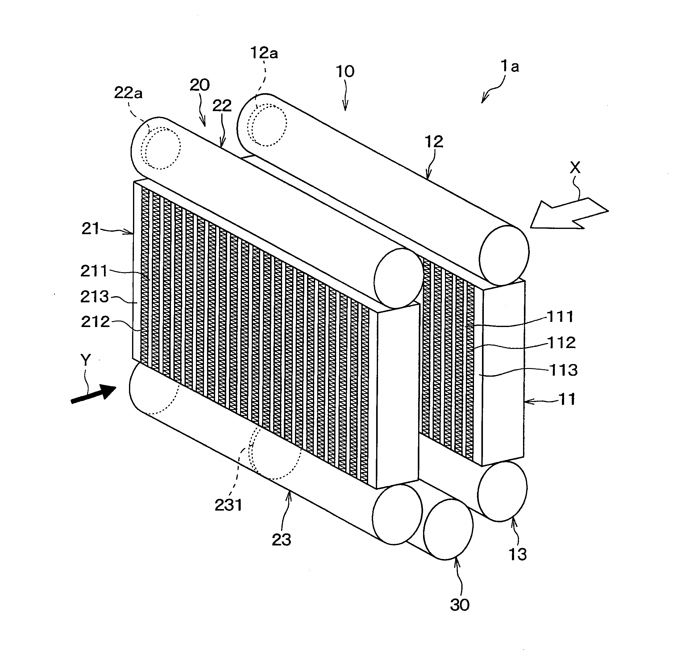
[0095]Referring now to FIG. 1 to FIG. 10, a first embodiment of the present disclosure will be described. A refrigerant evaporator 1a of the present embodiment is applied to a vapor compression refrigerating cycle of a vehicle air-conditioning apparatus configured to adjust the temperature in a cabin, and is a cooling heat exchanger configured to cool blast air by absorbing heat from the blast air supplied into the cabin and evaporating refrigerant (liquid-phase refrigerant). In the present embodiment, the blast air corresponds to “a subject-to-cooling fluid flowing outside”.

[0096]A refrigerating cycle includes a compressor, a heat radiator (condenser), and an expansion valve, which are not illustrated, in addition to the refrigerant evaporator 1a, which are well known and, in the present embodiment, is used as a receiver cycle which includes a liquid receiver arranged between the heat radiator and the expansion valve.

[0097]FIG. 1 is a schematic perspective view of the refrigerant e...

second embodiment

[0171]Subsequently, a second embodiment of the present disclosure will be described. In the present embodiment, the configurations of the third and fourth coupling members 32a, 32b are different from those in the first embodiment. In the present embodiment, description of parts which are the same as or equivalent to those of the first embodiment is omitted, or is given briefly.

[0172]FIG. 11 is an explanatory drawing for explaining the third and fourth coupling members 32a, 32b according to the present embodiment.

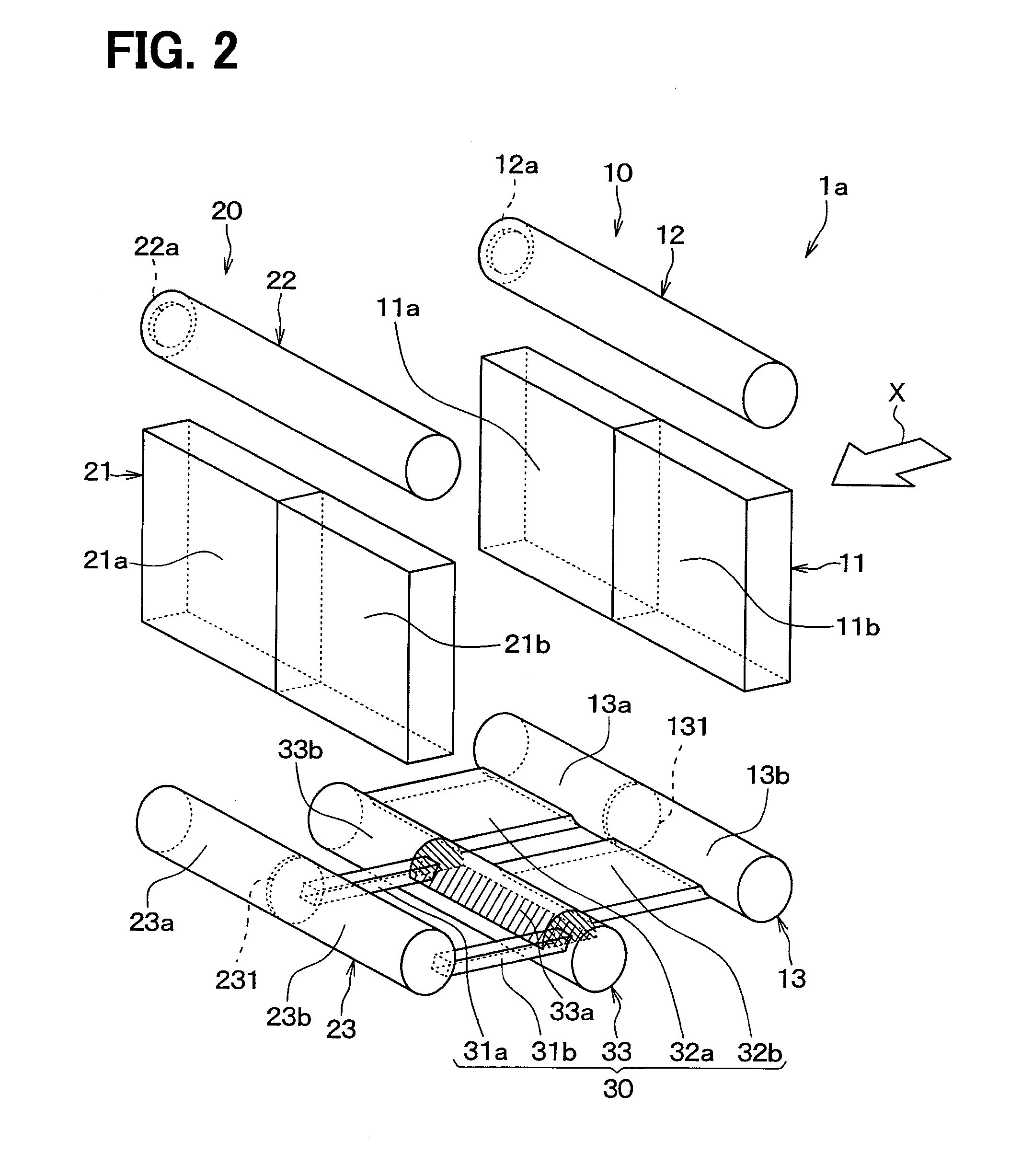
[0173]As illustrated in FIG. 11(a), in the present embodiment, the third and fourth coupling members 32a, 32b each include multiple coupling members (three coupling members in the present embodiment). The multiple coupling members each includes a cylindrical member having a refrigerant passage in which the refrigerant flows inside thereof, and is connected at one end side to the second windward tank unit 13 and at the other end side to the intermediate tank unit 33.

[0174]As ...

third embodiment

[0177]Subsequently, a third embodiment of the present disclosure will be described. The present embodiment is different from the first embodiment in the opening widths of the third and fourth coupling members 32a, 32b of the refrigerant exchanging portion 30. In the present embodiment, a description of parts which are the same as or equivalent to those of the first and second embodiments is omitted, or is given briefly.

[0178]As described in conjunction with the first embodiment, in the refrigerant evaporator 1a according to the comparative example, the distributing properties of the liquid-phase refrigerant to the second windward core portion 11b of the windward heat exchanging core unit 11 are not good, and when viewing in the blast air flowing direction X, a portion where the liquid-phase refrigerant can hardly flow is generated in the second windward core portion 11b (see FIG. 7(c)).

[0179]Accordingly, in the present embodiment, as shown in FIG. 12, the opening width Lb2 of the fo...


PUM


Abstract

A refrigerant evaporator includes four core portions. A part of the refrigerant passes through a first core portion and a fourth core portion. The other part of the refrigerant passes through a second core portion and a third core portion. An exchanging unit exchanges the positions where the refrigerant flows. A passage through which the second core portion communicates with the third core portion includes a throttle passage in the intermediate tank unit. The throttle passage and the end portion of the intermediate tank unit reverse the refrigerant flow toward a partitioning member. Since the distribution of a liquid-phase refrigerant is adjusted by the throttle passage, a concentration of the liquid-phase refrigerant on a position in the vicinity of an outlet of the third core portion is suppressed. Accordingly, the concentration of the liquid-phase refrigerant in the core portions located downstream of the refrigerant flow is suppressed.

Description

CROSS REFERENCE TO RELATED APPLICATION[0001]This application is based on and incorporates herein by reference Japanese Patent Applications No. 2011-240411 filed on Nov. 1, 2011, and No. 2012-049573 filed on Mar. 6, 2012.TECHNICAL FIELD[0002]The present disclosure relates to a refrigerant evaporator that cools a subject-to-cooling fluid by absorbing heat from the subject-to-cooling fluid and causes refrigerant to evaporate.BACKGROUND ART[0003]A refrigerant evaporator functions as a cooling heat exchanger configured to cool a subject-to-cooling fluid (for example, air) by absorbing heat from the subject-to-cooling fluid flowing outside to evaporate the refrigerant (liquid-phase refrigerant) flowing inside.[0004]Examples of the known refrigerant evaporator of this type include a configuration in which first and second evaporators each provided with a heat exchanging core unit having multiple stacked tubes and a pair of tank units connected to both end portions of the multiple tubes are...

Claims


Application Information

Patent Timeline
Patent Type & Authority Applications(United States)
IPC IPC(8): F25B5/00F28D1/053
CPCF28D1/05308F25B5/00F25B39/02F28D1/05391
Inventor ISHIZAKA, NAOHISABABA, NORIMASAKAMEI, ICHIOKAZARI, KENGOCHATANI, SHOTA
Owner DENSO CORP
Why Eureka
Try Eureka