Resin fan

a technology of a fan and a body is applied in the field of resin fans, which can solve the problems of reducing the strength of the fan, reducing the production efficiency, and indiscriminately reducing the wall thickness, and achieve the effect of mechanical strength in the junction portion

Active Publication Date: 2013-12-03
MITSUBISHI HEAVY IND LTD
View PDF7 Cites 4 Cited by
  • Summary
  • Abstract
  • Description
  • Claims
  • Application Information

AI Technical Summary

Benefits of technology

[0018]According to the present invention, in the resin agitating part comprising the convex part formed on the tubular rib, the gradient of thickness of the tubular rib, the protrusion of the tubular rib with respect to the radial ribs, and the like, the resin flow at the time when the resin having passed through the one radial rib forming portion and the resin having passed through the other radial rib forming portion join together can be complicated three-dimensionally. Thereby, the orientation of glass fiber contained in both of the resins can be complicated. As a result, the mechanical strength in the junction portion where the resin having passed through the one radial rib forming portion and the resin having passed through the other radial rib forming portion join together can be enhanced.

Problems solved by technology

However, because of the manufacturing method of resin molding, if the wall thicknesses of fan parts increase, the cooling after resin molding takes much time, which leads to a decrease in production efficiency.
On the other hand, the decrease in wall thickness leads to a decrease in fan strength.
Thus, it is a matter of course that it is unpreferable to decrease the wall thickness indiscriminately.
If a weld is present in a stress concentrated portion, damage such as a crack occurs easily in the weld part.

Method used


Image

  • Resin fan
  • Resin fan
  • Resin fan

Examples


example 1

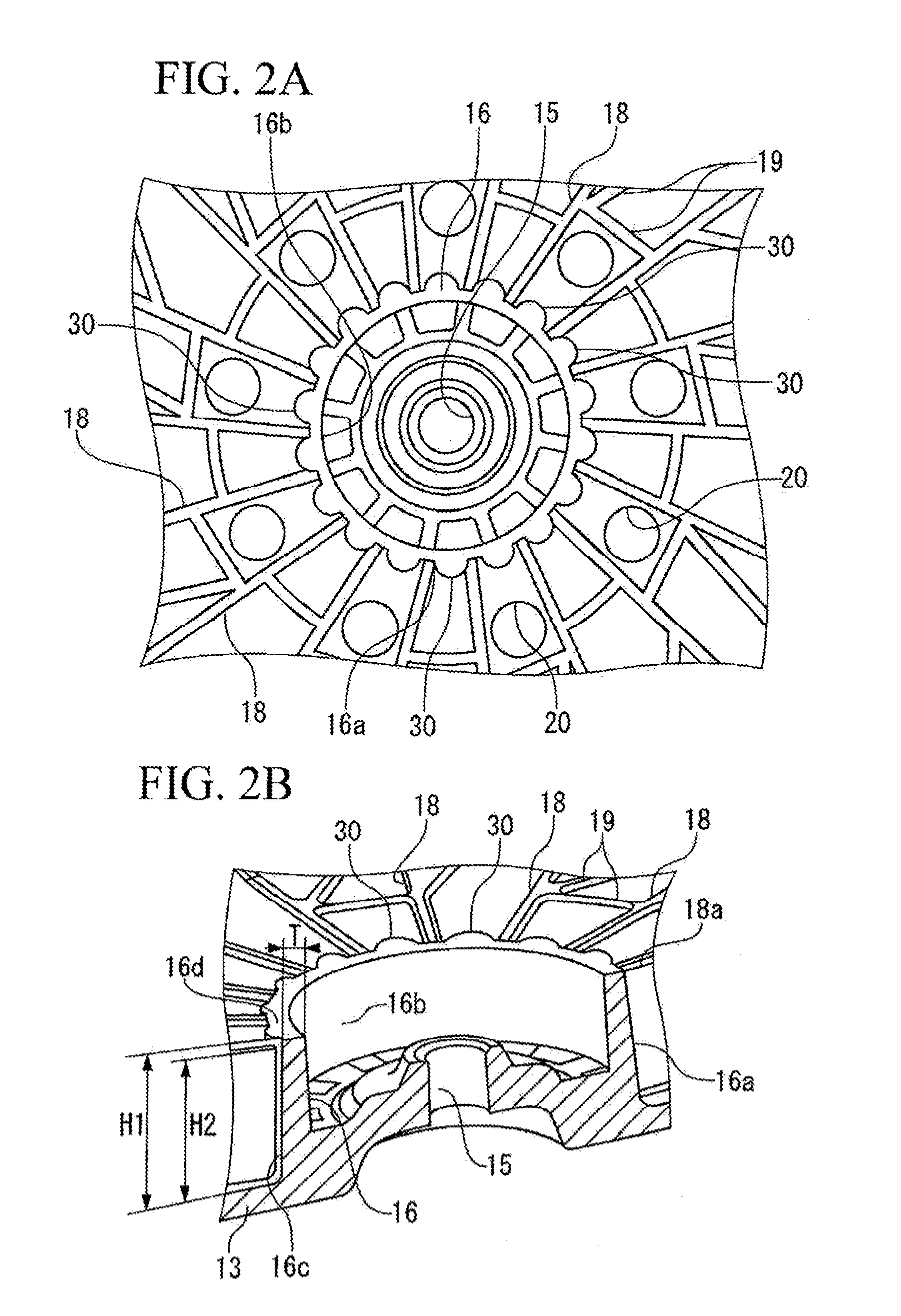
[0042]Studies were conducted on the effect in the case where the convex parts 30 were formed, the cylindrical rib 16 was formed so that the thickness T thereof was decreased gradually from the base part 16c toward the tip end part 16d, and further the height H1 of the cylindrical rib 16 was set so as to be larger than the height H2 of the radial rib 18 as described above. The study results are shown below.

working example

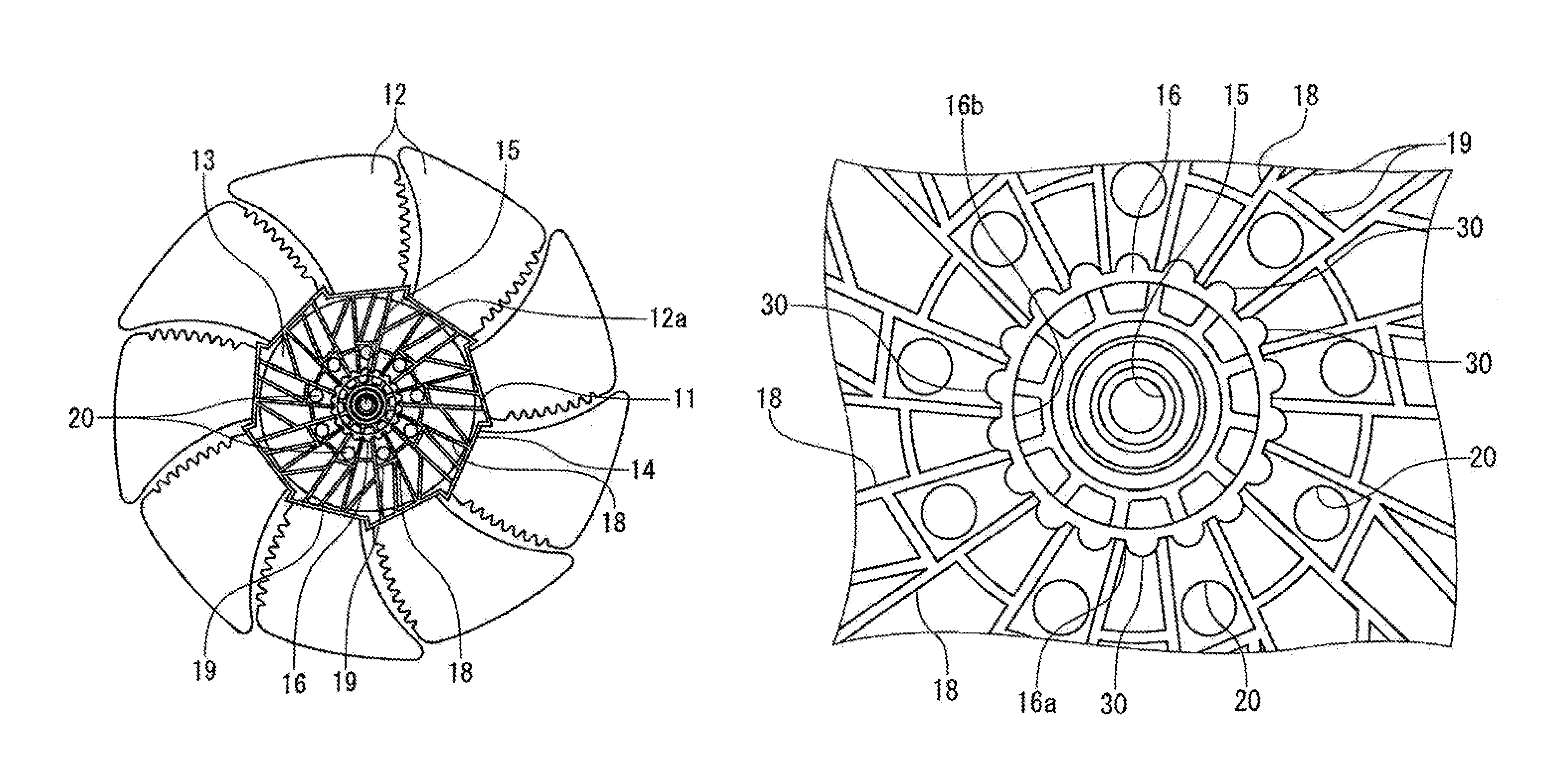
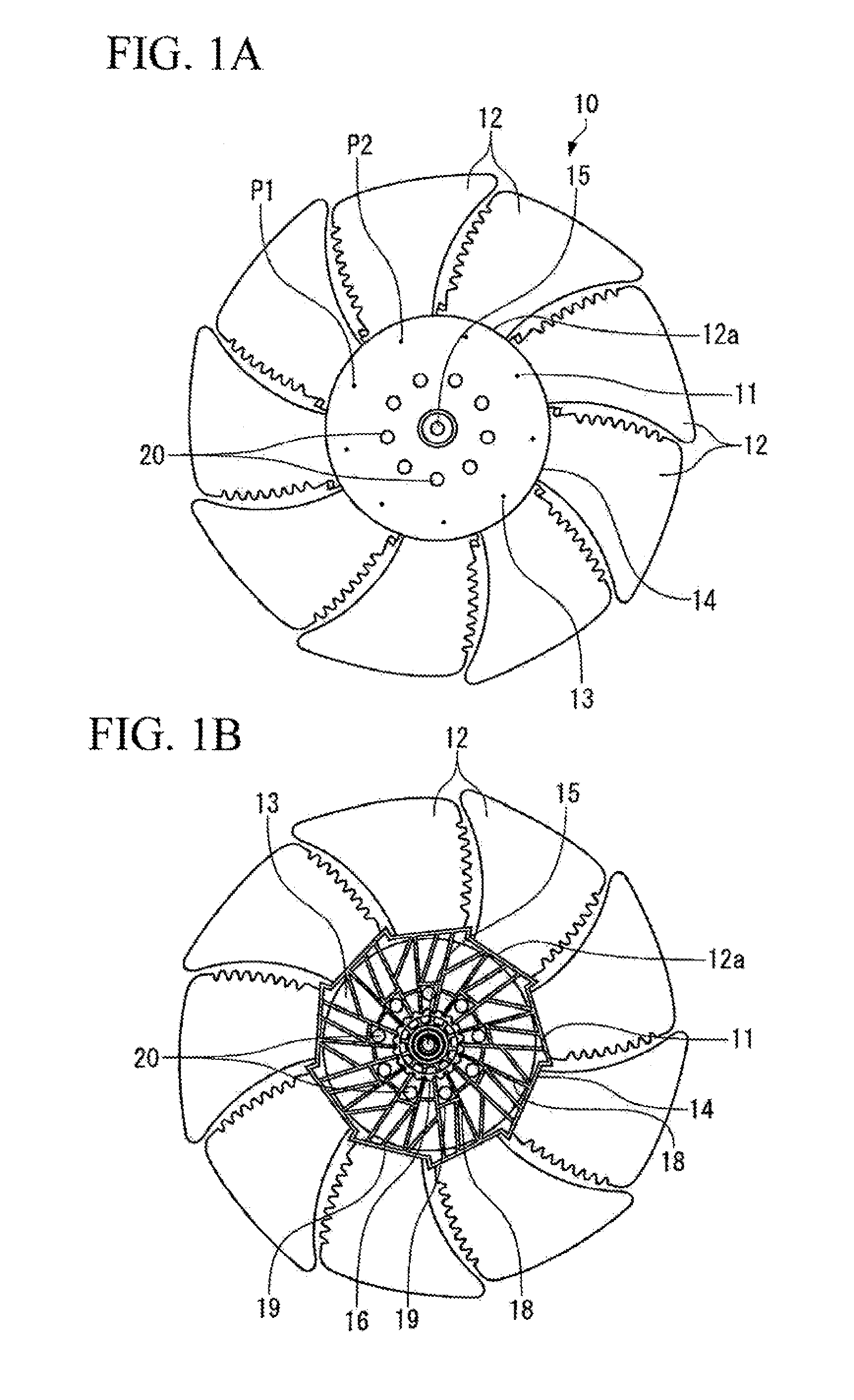
[0043]The fan 10 shown in FIG. 1 was made of polypropylene (pp) containing 30% glass fiber. For the fan 10, on the outer peripheral surface 16a of the cylindrical rib 16 having a diameter of 35 mm, the convex parts 30 were formed in the middle portions between the portions in which the radial ribs 18 adjoining each other were connected to the cylindrical rib 16. The curvature radius R of the convex part 30 was set at 1.25 mm, and the curvature radius r of the connecting part of the cylindrical rib 16 and the convex part 30 was set at 1.0 mm. Also, the cylindrical rib 16 was formed at an angle θ of 3 degrees so that the thickness T in the radial direction thereof was decreased gradually from the base part 16c toward the tip end part 16d. The thickness T of the tip end part 16d was set at 2.5 mm. Further, the height H1 of the cylindrical rib 16 was set at 13.5 mm and the height H2 of the radial rib 18 was set at 12.5 mm so that the cylindrical rib 16 is taller than the radial rib 18.


PUM

PropertyMeasurementUnit
height H2aaaaaaaaaa
diameteraaaaaaaaaa
curvature radiusaaaaaaaaaa

Abstract

There is provided a resin fan capable of enhancing the mechanical strength in a weld part in view of the direction of reinforcing fiber. On the outer peripheral surface 16a of a cylindrical rib 16, convex parts 30 are formed in the middle portions between the portions in which radial ribs 18 adjoining each other are connected to the cylindrical rib 16. The cylindrical rib 16 is formed so that the thickness T in the radial direction thereof is decreased gradually from the base part 16c thereof toward the tip end part 16d. Further, the height H1 of the cylindrical rib 16 is set so as to be larger than the height H2 of the radial rib 18. Thereby, at the time of molding, the resin flows in the portions of the cylindrical rib 16 and the convex parts 30 are complicated, and thereby the orientation of glass fiber mixed in the resin is complicated.

Description

TECHNICAL FIELD[0001]The present invention relates to a resin fan equipped to cool a radiator or an air conditioning condenser.BACKGROUND ART[0002]A fan equipped to cool a vehicular radiator or an air conditioning condenser is generally formed by resin molding.[0003]For the fan of this type, the shape and dimensions thereof have been designed focusing on enhancing the performance. However, because of the manufacturing method of resin molding, if the wall thicknesses of fan parts increase, the cooling after resin molding takes much time, which leads to a decrease in production efficiency. Therefore, it is preferable that the wall thicknesses of fan parts be as small as possible. The same holds true for reduction in weight. On the other hand, the decrease in wall thickness leads to a decrease in fan strength. As far as the product quality goes, a strength sufficient to prevent breakage or the like from occurring after the start of service is required. Thus, it is a matter of course th...

Claims


Application Information

Patent Timeline
Patent Type & Authority Patents(United States)
IPC IPC(8): F04D29/32
CPCB29C45/0005B29C45/0046F04D29/023F04D29/329F04D29/386B29C45/0025F04D29/325B29L2031/08B29L2031/087B29C33/3835B29C2045/0044F05D2300/44F05D2300/6034
Inventor BESSHO, MASAHIROHIMENO, TAKAMITSUSUZUKI, ATSUSHIKOBAYASHI, TAKAYUKIOKAMOTO, KIMIHIKO
Owner MITSUBISHI HEAVY IND LTD
Why Eureka
Try Eureka