
Supercharging feed system and method for a belt in tube conveyor

a tube conveyor and feed system technology, applied in the direction of mowers, agriculture tools and machines, mowers, etc., can solve the problems of affecting the speed of unloading, affecting the speed of material movement, and crop material damage between, so as to avoid associated drag and further disruption or impedance of flow, the effect of reducing the disturbance of flow and avoiding the disruption of flow

Active Publication Date: 2015-01-29
BLUE LEAF I P INC
View PDF19 Cites 23 Cited by
  • Summary
  • Abstract
  • Description
  • Claims
  • Application Information

AI Technical Summary

Benefits of technology

The invention is a system for delivering crop material to a conveyor belt in a tube conveyor. The system includes a crop delivery apparatus that propels the crop material at a speed that matches or exceeds the speed of the belt. This ensures that the crop material is directed into the belt and deposited on the concave portion of the belt without changing direction or losing velocity. The system also includes an upper portion of the conveyor that acts as a guide to contain the crop material flow and prevent it from spreading or disrupting the flow. The crop material is delivered to the belt in a way that allows it to be easily accelerated and unloaded, without causing significant damage or disruption to the flow. The system is advantageous in that it allows for improved fill capability and unloading capabilities compared to traditional methods of delivery.

Problems solved by technology

However, this manner of unloading has been found to be slower than desired for many agricultural operations.
Also, as a consequence of necessary spacing between the auger flight edges and the interior surface of the unloading tube, the crop material can be damaged therebetween.
As the belt is transitioned to the concave shape while carrying material, some of the material will be lifted and shifted laterally toward the center of the belt, possibly while additional material is deposited onto it, such that turbulence can occur that will impede movement and acceleration of the material to the belt speed, which can decrease the effective capacity of the conveyor and conveying speed.
As a result, use of belt in tube conveyors for unloading applications has been found to suffer from shortcomings in terms of speed and / or capacity.

Method used


Image

  • Supercharging feed system and method for a belt in tube conveyor
  • Supercharging feed system and method for a belt in tube conveyor
  • Supercharging feed system and method for a belt in tube conveyor

Examples


Embodiment Construction

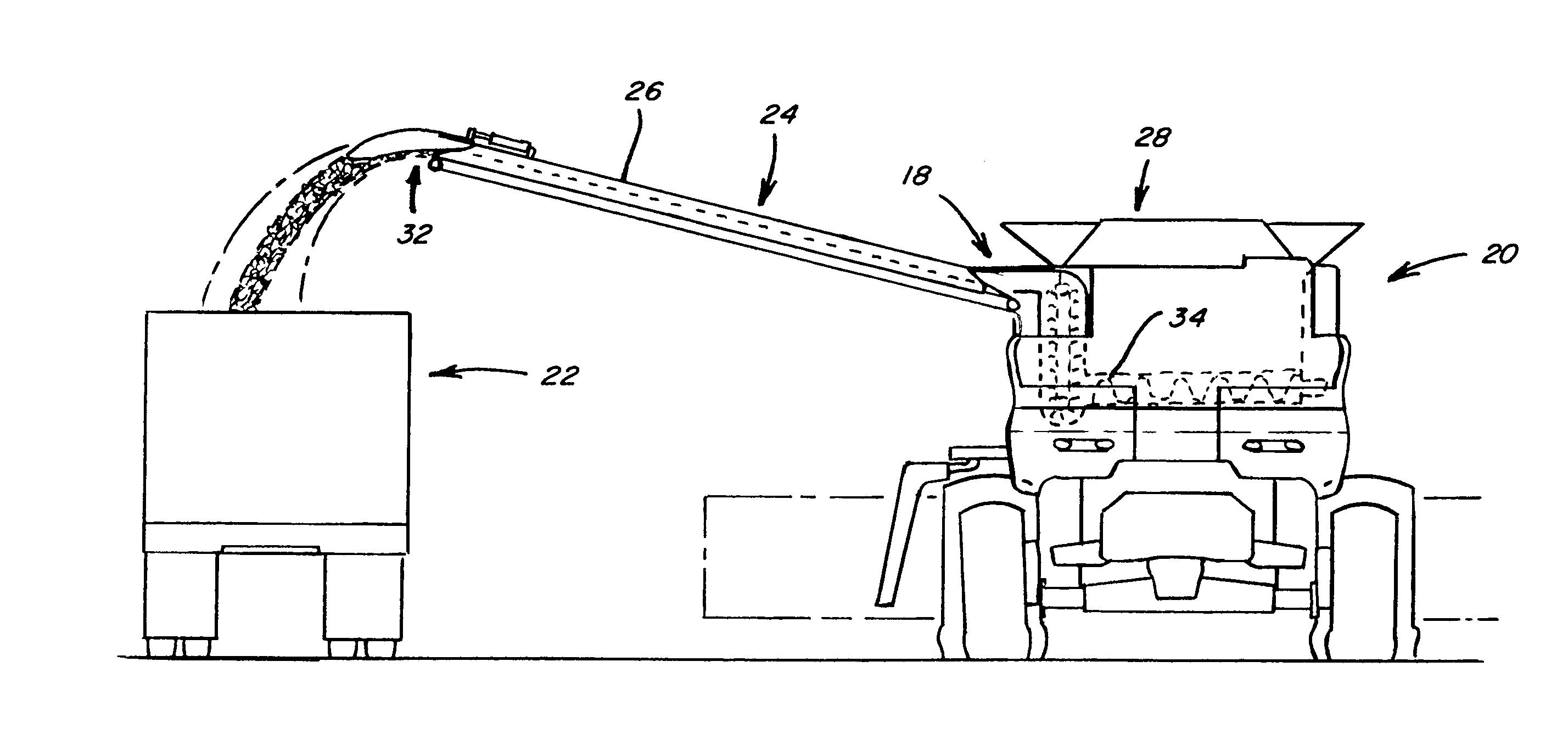
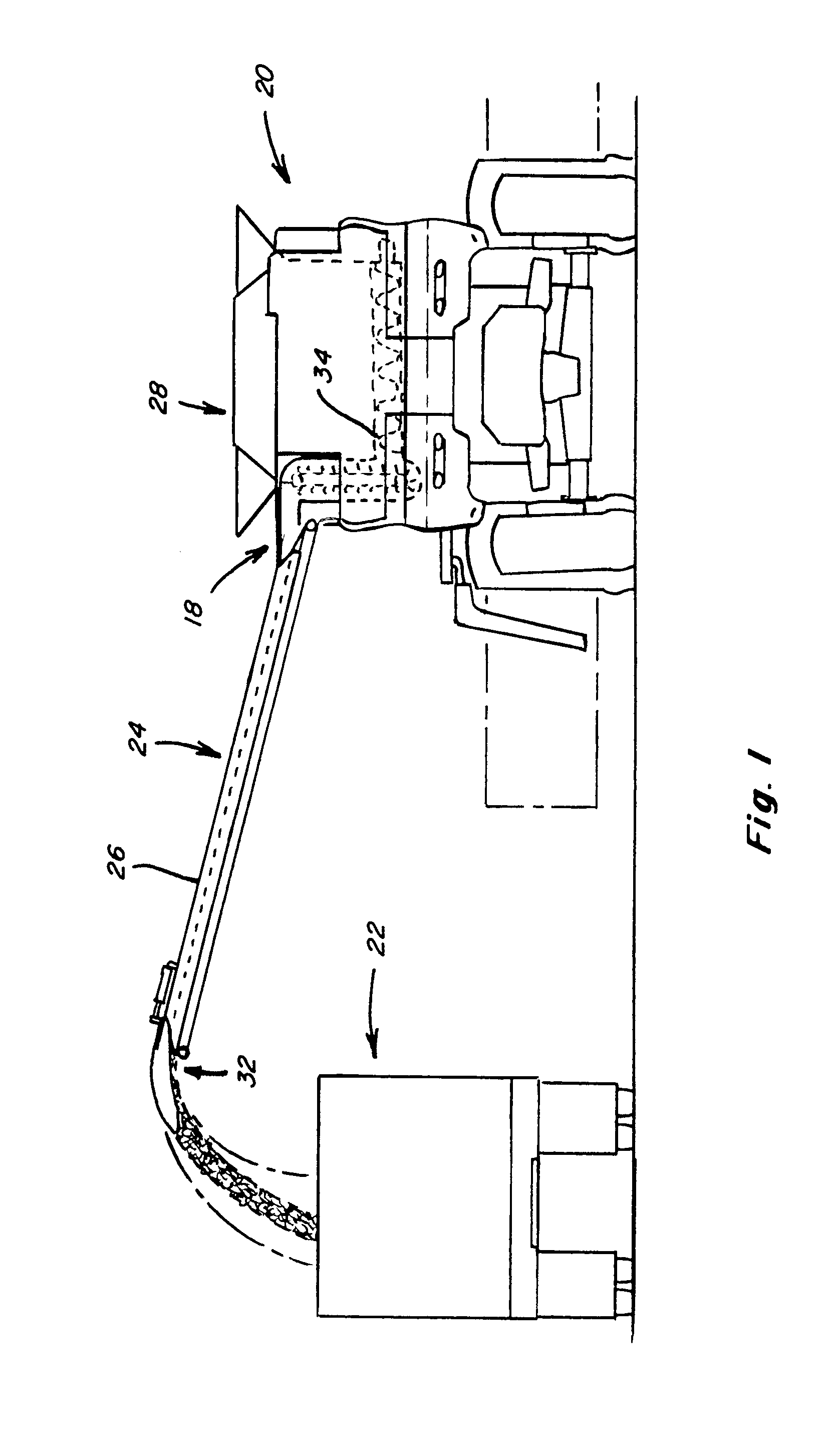
[0025]Referring now to the drawings, wherein like numbers refer to like items, FIG. 1 depicts a supercharging feed system 18 constructed and operable according to the teachings of the invention, incorporated onto a representative agricultural vehicle, which is shown here as a combine 20, in association with a belt in tube conveyor system 24 adapted for use as an unloading conveyor for combine 20. Belt in tube conveyor system 24 is shown in a deployed position extending sidewardly outwardly from combine 20, for unloading crop material from an on board grain tank 28 or other container, into an accompanying receiving container 22, such as a tractor pulled cart, wagon, trailer, or, in this case, a truck. As can be observed in FIG. 1, conveyor system 24 is advantageously inclined upwardly and outwardly relative to combine 20, to provide clearance for passage and placement over a variety of receiving containers, including when on side hills and other uneven or inclined surfaces and the li...


PUM


Abstract

A system and method for supercharging the feed system for a belt in tube conveyor for agricultural products, which enables achieving a full or near full fill level of the conveyor belt entering the intake end of the conveyor tube. The invention uses a crop delivery apparatus operable to propel an airborne flow of the crop material at least largely in a direction of movement of the conveyor belt, onto the belt surface after formation into a concave shape conforming to a lower portion of the conveyor tube. Additional capabilities include the ability to propel the crop material into an intake end of the conveyor tube, and provision of enclosing structure for containing and focusing the crop material flow. The system can accommodate various angles of tilt and sideward pivotal movement of the conveyor.

Description

TECHNICAL FIELD[0001]The present invention relates to automated conveying systems, and more particularly to a system and method for supercharging a belt in tube conveyor for agricultural products, to enable achieving a full or increased fill level of the belt entering the intake end of the conveyor tube. The supercharging is achieved by propelling the crop material onto the conveyor belt or the material previously deposited on the belt, substantially, or at least largely, in a direction of movement of the belt, and after the belt has been at least substantially transitioned into a concave shape for passage through the tube, such that significant directional change or movement in a direction other than the direction of movement of the belt, are avoided.BACKGROUND ART[0002]To increase productivity, agricultural vehicles, such as combines, are becoming larger, headers are becoming wider, and travel speeds are increasing during harvest. Additionally, harvesting operations in a large fie...

Claims


Application Information

Patent Timeline
IPC IPC(8): B65G15/08
CPCB65G15/08A01D41/1217
Inventor PRIEPKE, EDWARD H.WILSON, SCOTT D.BORSDORF, JOHN J.RICKETTS, JONATHAN E.
Owner BLUE LEAF I P INC
Learn More