Charging cable

Active Publication Date: 2015-01-29
PANASONIC INTELLECTUAL PROPERTY MANAGEMENT CO LTD
View PDF7 Cites 15 Cited by
  • Summary
  • Abstract
  • Description
  • Claims
  • Application Information

AI Technical Summary

Benefits of technology

The present invention aims to provide a charging cable for an electric propulsion vehicle that can prevent overheating and allow for a longer charging period.

Problems solved by technology

Thus, slow charging facilities using commercial 100- or 200-V power supplies have started to be introduced into households, offices, and the like.
The charging cable for the electric propulsion vehicle may suffer abnormal heat generation caused by an incomplete connection between the electric outlet and the power plug or a tracking phenomenon.
However, the charging cable in Patent Document 1 fails to definitely describe the recovery of the temporarily stopped power supply.
Thus, even when abnormal heat generation occurs, termination of the charging prevents satisfaction of the demand to ensure as long a period of charging as possible.

Method used


Image

  • Charging cable
  • Charging cable
  • Charging cable

Examples


embodiment 1

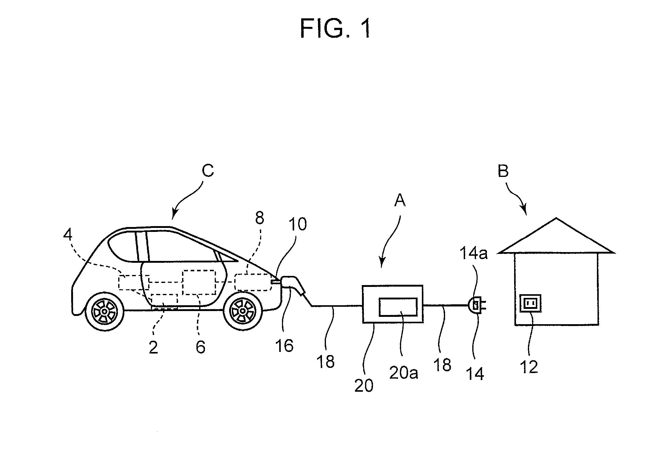
[0023]Embodiment 1 of the present invention will be described below with reference to the drawings. FIG. 1 is a diagram of a general configuration of a charging system to which a charging cable A for an electric propulsion vehicle according to Embodiment 1 of the present invention is applied. In the charging system, an electric propulsion vehicle C is powered using a commercial power supply at a standard home B via the charging cable A, to charge a battery 6 for the electric propulsion vehicle C.

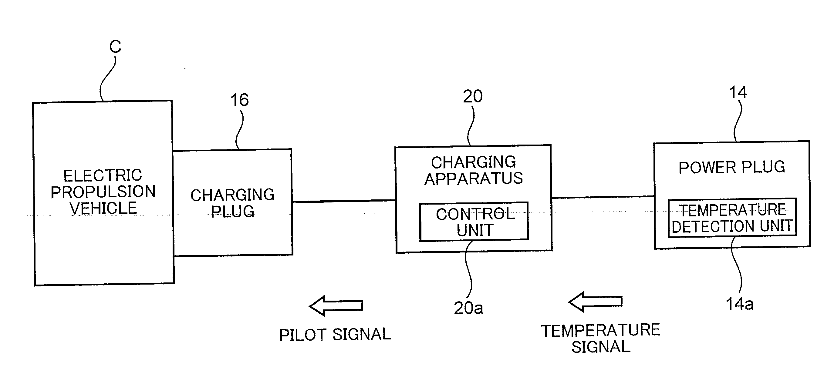
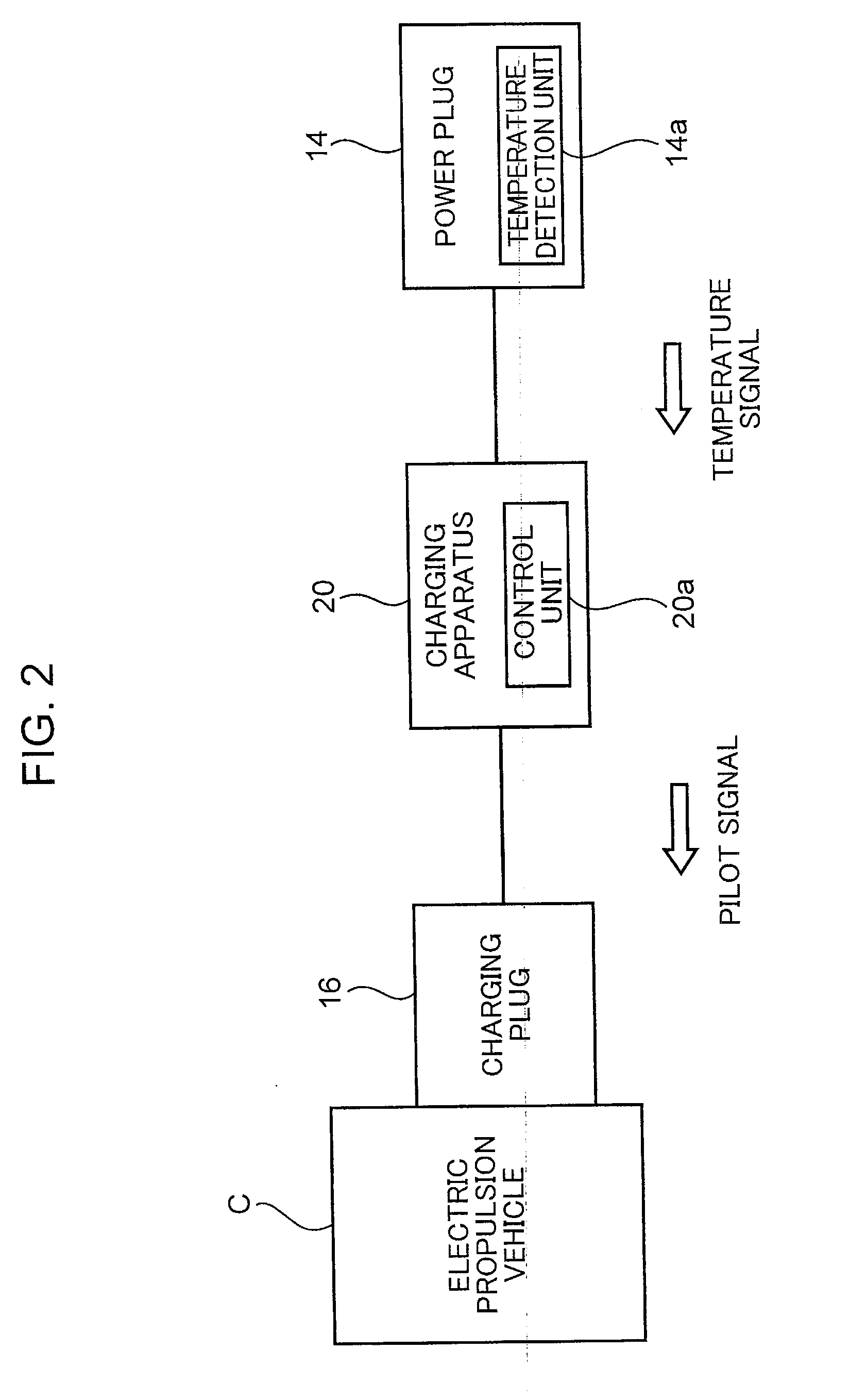
[0024]As shown in FIG. 1, the electric propulsion vehicle C includes a drive motor 2, an inverter 4, the battery 6, and a charging control apparatus 8. The drive motor 2, the inverter 4, the battery 6, and the charging control apparatus 8 are electrically connected together. The electric propulsion vehicle C is connected to the charging cable A via a connector 10 connected to the charging control apparatus 8.

[0025]The drive motor 2 is a motor that drives the electric propulsion vehicle C. Th...

embodiment 2

[0053]The charging cable A according to Embodiment 2 is characterized by avoiding the recovery of the electric conduction to the battery 6 even when the detected temperature decreases to the specified temperature T2 or lower if the detected temperature during the period of electric conduction has a temperature gradient equal to or larger than a predetermined specified temperature gradient. Components of Embodiment 2 which are the same as the corresponding components of Embodiment 1 are denoted by the same reference numerals and will not be described.

[0054]Control according to Embodiment 2 will be described using FIG. 4. In Embodiment 2, the control unit 20a calculates the temperature gradient during a period of electric conduction TM1. Each time the temperature detection unit 14a transmits a detected temperature to the control unit 20a during the period of electric conduction TM1, the control unit 20a determines the difference between the currently transmitted detected temperature a...

embodiment 3

[0058]The charging cable A according to Embodiment 3 is characterized by reducing the conduction current compared to a value used before the stop of the electric conduction to the battery 6 when the electric conduction is to be recovered. Components of Embodiment 3 which are the same as the corresponding components of Embodiments 1 and 2 are denoted by the same reference numerals and will not be described.

[0059]FIG. 5 are waveform diagram showing a control sequence for the charging cable A according to Embodiment 3 of the present invention. FIG. 5A shows the temporal transition of the detected temperature, and FIG. 5B shows the temporal transition of the conduction current. In FIG. 5A, the axis of ordinate indicates the detected temperature, and the axis of abscissas indicates time. In FIG. 5B, the axis of ordinate indicates the conduction current, and the axis of abscissas indicates time.

[0060]FIG. 5A and FIG. 5B are the same as FIG. 4A and FIG. 4B in that the electric conduction i...


PUM


Abstract

A temperature detection unit detects the temperature of a power plug. A control unit stops electric conduction to a battery when the detected temperature detected by the temperature detection unit is equal to or higher than a predetermined specified temperature (T1). The control unit recovers the electric conduction to the battery when the detected temperature detected by the temperature detection unit decreases to a specified temperature (T2) or lower, the specified temperature (T2) being lower than the specified temperature (T1).

Description

TECHNICAL FIELD[0001]The present invention relates to a charging cable for an electric propulsion vehicle such as an electric car or a hybrid car, the charging cable being used to charge a battery for the electric propulsion vehicle.BACKGROUND ART[0002]In recent years, electric propulsion vehicles known as environment-friendly cars have been developed at a rapid rate. Charging infrastructures for electric propulsion vehicles are roughly classified into two types of charging facilities: home charging facilities utilizing home power supplies that are terminals of a power network; and public charging facilities provided, for example, in urban areas or under road surfaces and based on the assumption that the facilities are used by the general public.[0003]With convenience taken into account, home charging facilities are needed in order to spread electric propulsion vehicles. Thus, slow charging facilities using commercial 100- or 200-V power supplies have started to be introduced into h...

Claims


Application Information

Patent Timeline
IPC IPC(8): H02J7/00B60L11/18
CPCH02J7/0029H02J2007/0039B60L11/1851B60L11/1818Y02T90/14H01M10/443H01M10/486B60L3/0023B60L3/0069B60L3/04B60L2210/30B60L2240/36H02J7/0031B60L2260/42Y04S30/14B60L53/16B60L50/51B60L53/65B60L53/18H02J7/00304B60L53/66Y02T10/70Y02T10/7072Y02T10/72Y02T90/12Y02T90/167Y02T90/16Y02E60/10
Inventor NISHIKAWA, MASANORIABE, NORIOKAWASE, TOMOYUKIAKAI, NARUAKISAWAHYOUDOU, TAKAAKI
Owner PANASONIC INTELLECTUAL PROPERTY MANAGEMENT CO LTD
Why Eureka
Try Eureka