Rare-Earth Magnet

a technology magnets, applied in the field of rare earth magnets, can solve the problems of dy market price jumping up, magnetization decreasing, and maximum energy product decreasing

Inactive Publication Date: 2015-01-29
HITACHI LTD
View PDF1 Cites 2 Cited by
  • Summary
  • Abstract
  • Description
  • Claims
  • Application Information

AI Technical Summary

Problems solved by technology

Therefore, there exists a problem that although coercivity of the Nd—Fe—B sintered magnet increases by addition of Dy, magnetization decreases and consequently the maximum energy product decreases as the amount of Dy added increases.
In addition, since a Dy content in a rare earth ore is low and its places of origin is unevenly distributed in China, there is a concern that when the Nd—Fe—B magnets are supplied in a large amount for HEV uses, Dy market price may jump up and actually result in impossibility of HEV production in near future.

Method used


Image

  • Rare-Earth Magnet
  • Rare-Earth Magnet
  • Rare-Earth Magnet

Examples


Embodiment Construction

[0021]The present invention will be illustrated in detail below referring to the drawings.

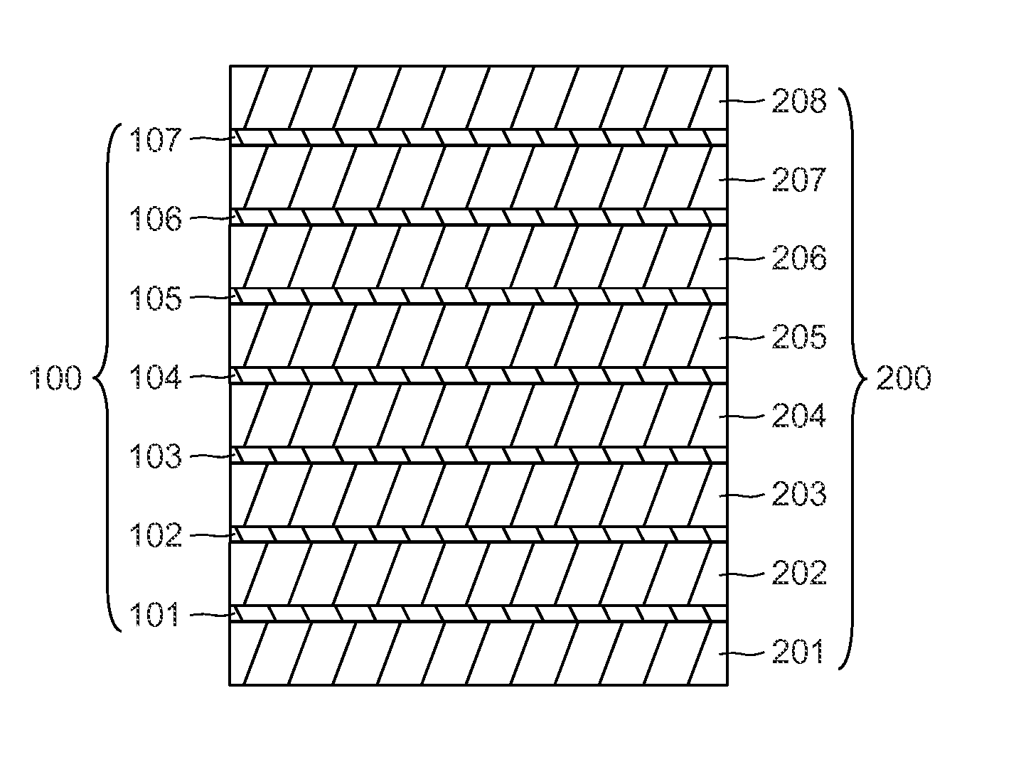
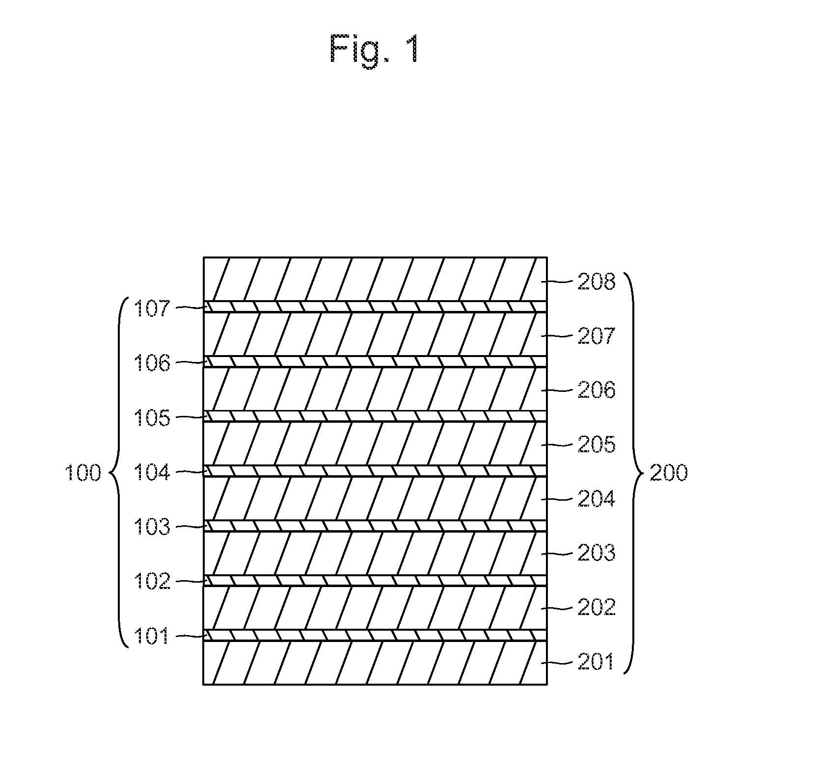
[0022]FIG. 1 shows a cross section structure of the main part of one embodiment of the rare-earth magnet according to the present invention. In FIG. 1, sheets of an element bonded with each other through a covalent bond 101, 102, 103, 104, 105, 106 and 107 (hereinafter, referred to as sheets 100) and layers consisting of transition metal element 201, 202, 203, 204, 205, 206, 207 and 208 (hereinafter, referred to as layers consisting of transition metal element 200) form a laminated structure. In the rare earth magnet having such a laminated structure, the easy axis of magnetization (c axis) is directed to the direction of lamination of the sheets 100 and the layers consisting of transition metal element 200.

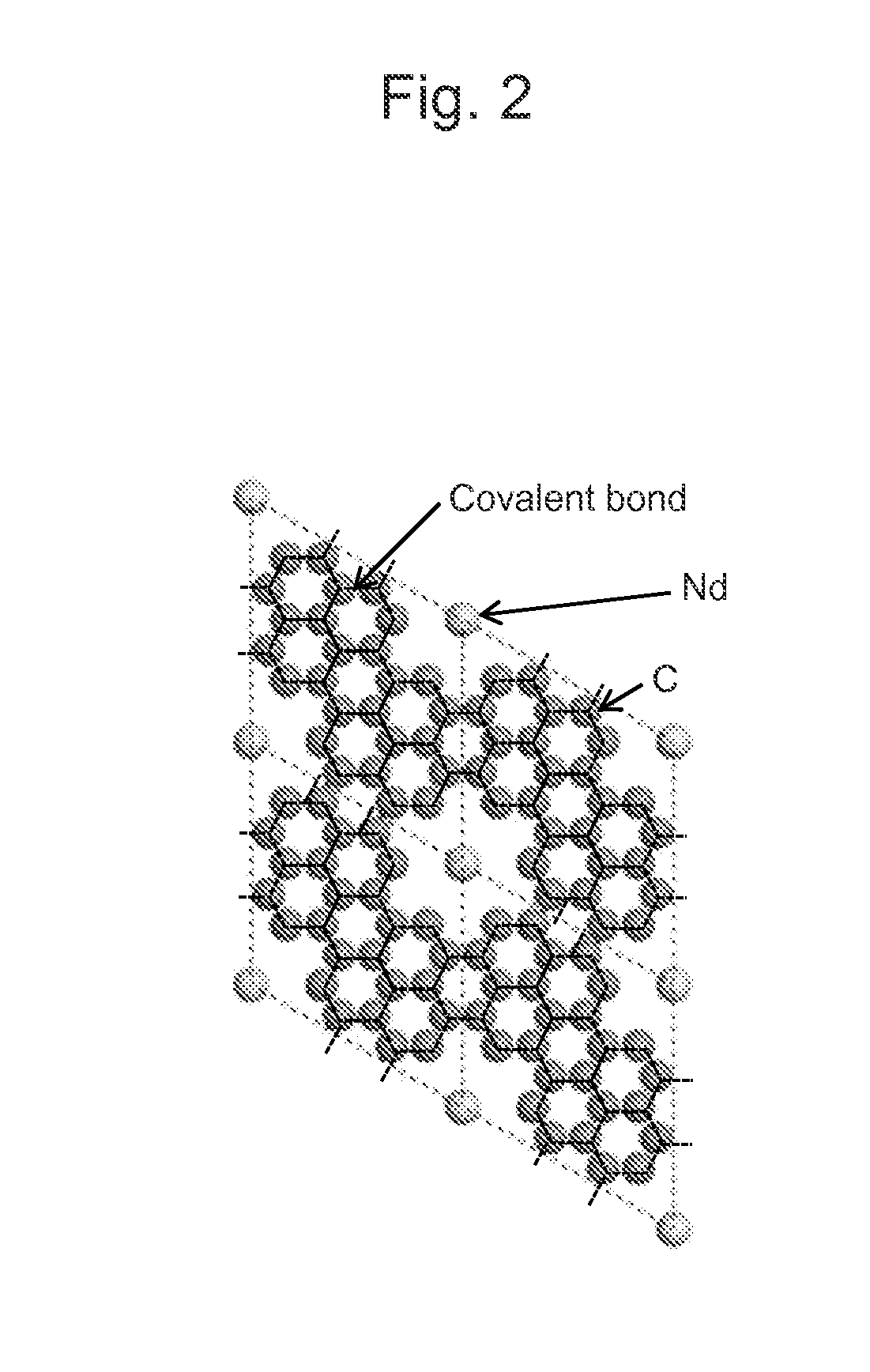
[0023]The element constituting the sheets 100 are at least one selected from the group consisting of, for example, C, Si and Ge. The rare earth element is, for example, at least one selected...


PUM

PropertyMeasurementUnit
distanceaaaaaaaaaa
distanceaaaaaaaaaa
distanceaaaaaaaaaa

Abstract

The purpose of the present invention is to provide a structure of a rare-earth magnet having high coercivity. In order to solve the problem, a rare-earth magnet according to the present invention comprises sheets of elements bonded with each other through a covalent bond 100 and layers comprising a transition metal element 200 laminated with the sheet 100, wherein a rare earth element is arranged within a plane of the sheets.

Description

TECHNICAL FIELD[0001]The present invention relates to a rare-earth magnet.BACKGROUND ART[0002]An Nd—Fe—B sintered magnet was invented in 1982, has been served as a permanent magnet material having the highest performance in the world up until now and employed in a number of products including voice coil motors (VCMs) for hard disc drives (HDDs), nuclear magnetic resonance imaging (MRI) apparatuses, and power generators. The production of the Nd—Fe—B sintered magnet has been on an upward trend particularly in applications for motors and power generators because of measures for energy-saving. Moreover, the Nd—Fe—B sintered magnet is the most promising magnetic material for large-sized driving motors in Hybrid Electric Vehicles (HEVs) which have been developed with consideration for environmental pollution, and therefore, further expanding production has been expected.[0003]A Maximum energy product and a coercivity are indexes indicating magnetic material performance. The maximum energ...

Claims


Application Information

Patent Timeline
Patent Type & Authority Applications(United States)
IPC IPC(8): H01F7/02H01F1/40H01F1/42
CPCH01F7/02H01F1/40H01F1/42H01F1/057H01F10/126H01F41/32C22C38/002C22C38/005C22C2202/02
Inventor MORIYA, HIROSHI
Owner HITACHI LTD
Why Eureka
Try Eureka