
Road surface management system

a technology of road surface management and management system, applied in the direction of navigation instruments, instruments, roads, etc., can solve the problems of excessive fuel consumption and tire wear, dump trucks suffer, and driver discomfor

Active Publication Date: 2015-01-29
NIHON KENKI CO LTD
View PDF5 Cites 25 Cited by
  • Summary
  • Abstract
  • Description
  • Claims
  • Application Information

AI Technical Summary

Benefits of technology

The patent allows for detecting and displaying road surfaces that tend to damage dump trucks. This helps to avoid damage to the trucks and ensures smooth operation on the road.

Problems solved by technology

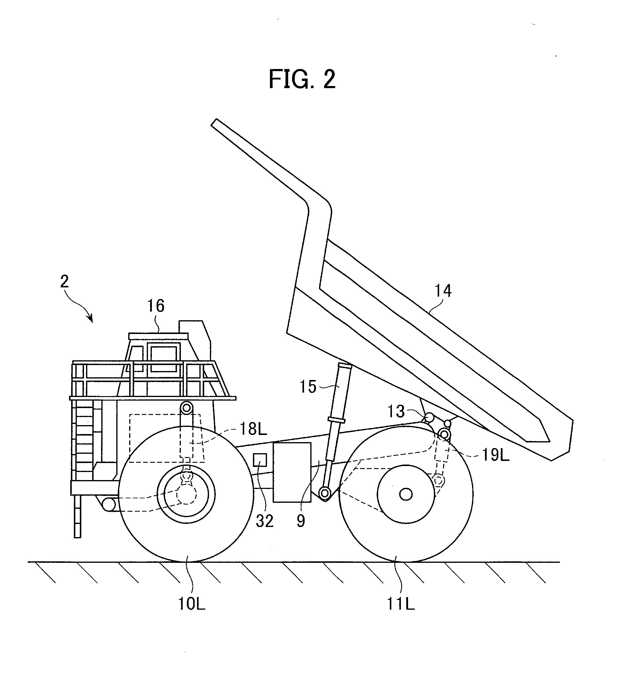
If the road surface of the traveling lane for the dump trucks has irregularities, the dump trucks suffer influences such as excessive fuel consumption and tire wear, as well as giving discomfort to the driver.

Method used


Image

  • Road surface management system
  • Road surface management system
  • Road surface management system

Examples


first embodiment

[0057]Although not particularly explained in the above first embodiment, the road surface information generation unit 25 of the server 4 may also be configured to evaluate the poor condition of the road surface in a stepped manner (stepped evaluation means) based on the magnitude of the influence coefficient outside the preset range in the case where one of the four influence coefficients β(FL), β(FR), β(RL) and β(RR) is judged to be outside the preset range (e.g., β17A and 17B by using different colors, different line types, etc. In such a modification (modified example), the priority order of the road surface maintenance / repair work can be determined with ease.

[0058]While the road surface information generation unit 25 of the server 4 of the management station3 in the above first embodiment makes the judgment on whether each of the pressures of the four suspensions 18L, 18R, 19L, and 19R is within the reference range which has been set for each suspension or not according to the a...

second embodiment

[0060]FIG. 8 is a block diagram partially showing the control configuration of a traffic management system in accordance with the present invention.

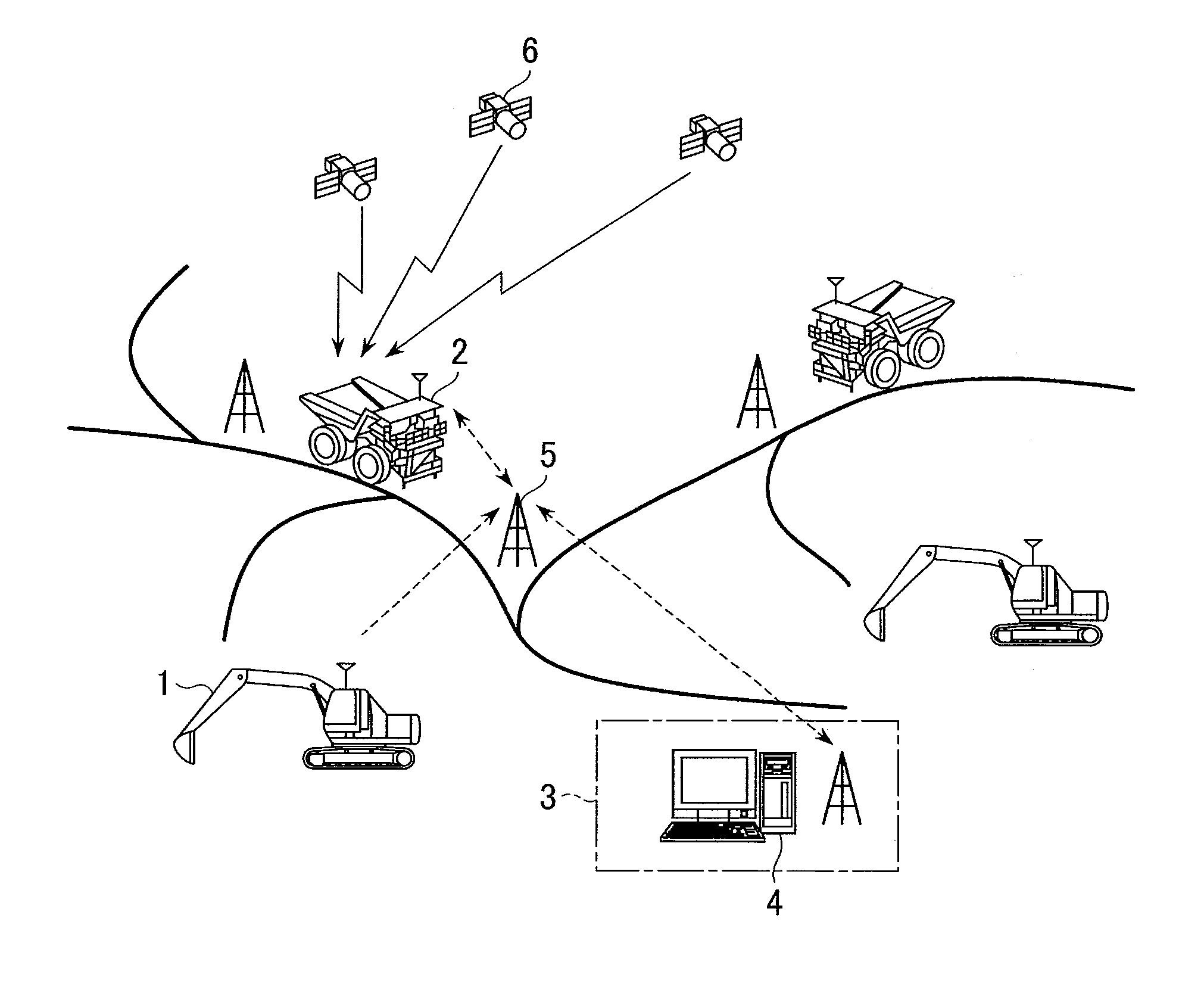
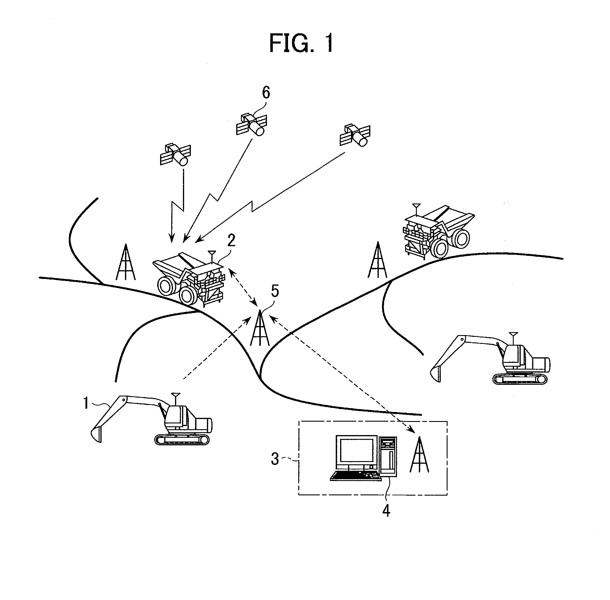
[0061]In this embodiment, a server 4A of the management station 3, communicating information with excavators 1, dump trucks 2 and motor graders 31 (examples of the road repair vehicles) via the radio relay stations 5, manages the positions of the excavators 1, the dump trucks 2 and the motor graders 31 while also managing the road surface condition of the traveling lanes for the dump trucks 2.

[0062]The motor grader 31 comprises a position calculation device 7C, a radio communication device 8D, a map storage device 22A and a display control device 23A. The position calculation device 7C calculates the current position of the motor grader 31 based on signals received from GPS satellites 6. The radio communication device 8D transmits the positional information of the motor grader 31 calculated by the position calculation device 7C to the ma...


PUM


Abstract

A road surface management system is capable of detecting road surface conditions that tend to damage dump trucks and displaying the positions of such road surfaces. When the traveling speed of the dump truck is higher than or equal to a preset threshold value, the server judges whether or not each of the pressures of suspensions of the dump truck detected by pressure sensors is within a reference range which has been set corresponding to each suspension. The server judges that the road surface at the position of a dump truck is in a poor condition if one of the pressures of the four suspensions of the dump truck is judged to be outside the reference range and the remaining three pressures are judged to be within the reference range. The positions of the road surfaces judged to be in the poor condition are displayed on an indicator.

Description

TECHNICAL FIELD[0001]The present invention relates to a road surface management system for managing the road surface condition of traveling lanes for dump trucks used in quarries or construction sites.BACKGROUND ART[0002]In quarries or construction sites, a plurality of dump trucks are operated in order to carry the excavated materials (rocks, earth, sand, etc.). Each dump truck travels on a traveling lane to and fro between the loading site and the unloading / dumping site. If the road surface of the traveling lane for the dump trucks has irregularities, the dump trucks suffer influences such as excessive fuel consumption and tire wear, as well as giving discomfort to the driver. In order to resolve such problems, a road surface repairing system for detecting and repairing the road surface irregularities has been proposed (see Patent Document 1, for example).[0003]In the road surface repairing system described in the Patent Document 1, a millimeter wave sensor is arranged at the fron...

Claims


Application Information

Patent Timeline
IPC IPC(8): G07C5/00G01C7/04G08G1/00E01C23/01G08G1/123
CPCG07C5/00E01C23/01G01C7/04G08G1/00G08G1/123B60W40/06B60W2510/22B60W2520/10B60W2556/50B60W2552/35
Inventor IKARI, TAKANOBU
Owner NIHON KENKI CO LTD
Learn More