Method For Regulating The De-Icing Of A Leading Edge Of An Aircraft And Device For Its Implementation

a leading edge and aircraft technology, applied in the direction of valve operating means/releasing devices, machines/engines, efficient propulsion technologies, etc., can solve the problems of insufficient satisfactory prior art regulator devices, damage to air intake, and ice may tend to form

Active Publication Date: 2015-02-05
AIRBUS OPERATIONS (SAS)
View PDF1 Cites 28 Cited by
  • Summary
  • Abstract
  • Description
  • Claims
  • Application Information

AI Technical Summary

Benefits of technology

[0026]Being able to regulate the flow of air in accordance with two regulation levels makes it possible, using a single source of hot air, to optimize the flow of hot air transmitted for de-icing the air intake and to adapt it notably as a function of the capabilities of the hot air source and / or surrounding conditions in order to obtain a flow of air sufficient to achieve de-icing without risk of damaging the air intake because of too high a temperature of the flow of hot air.

Problems solved by technology

Under some conditions, frost or ice may tend to form at the level of the air intake.
On the other hand, too high a temperature and / or pressure may damage the air intake, which is generally made from composite materials and / or aluminum alloy.
Even if it has numerous advantages, the prior art regulator device cannot be fully satisfactory because regulation can be effected only in accordance with a single regulation level.
Accordingly, in certain circumstances, for example for certain engines, it is not possible with a single regulation level to arrive at a compromise between effective de-icing and the maximum temperature and pressure acceptable by the air intake for all flight phases.
This solution is not entirely satisfactory because it leads to a more costly and more complex architecture that is not suitable for an engine environment that is already subject to severe constraints in terms of available space, temperature and vibration.
However, this solution is relatively costly and complex and leads to an increase in the onboard mass.
This solution is not entirely satisfactory because it leads to considerably increased complexity of the control logic, valve technology level and system control.

Method used


Image

  • Method For Regulating The De-Icing Of A Leading Edge Of An Aircraft And Device For Its Implementation
  • Method For Regulating The De-Icing Of A Leading Edge Of An Aircraft And Device For Its Implementation
  • Method For Regulating The De-Icing Of A Leading Edge Of An Aircraft And Device For Its Implementation

Examples


Embodiment Construction

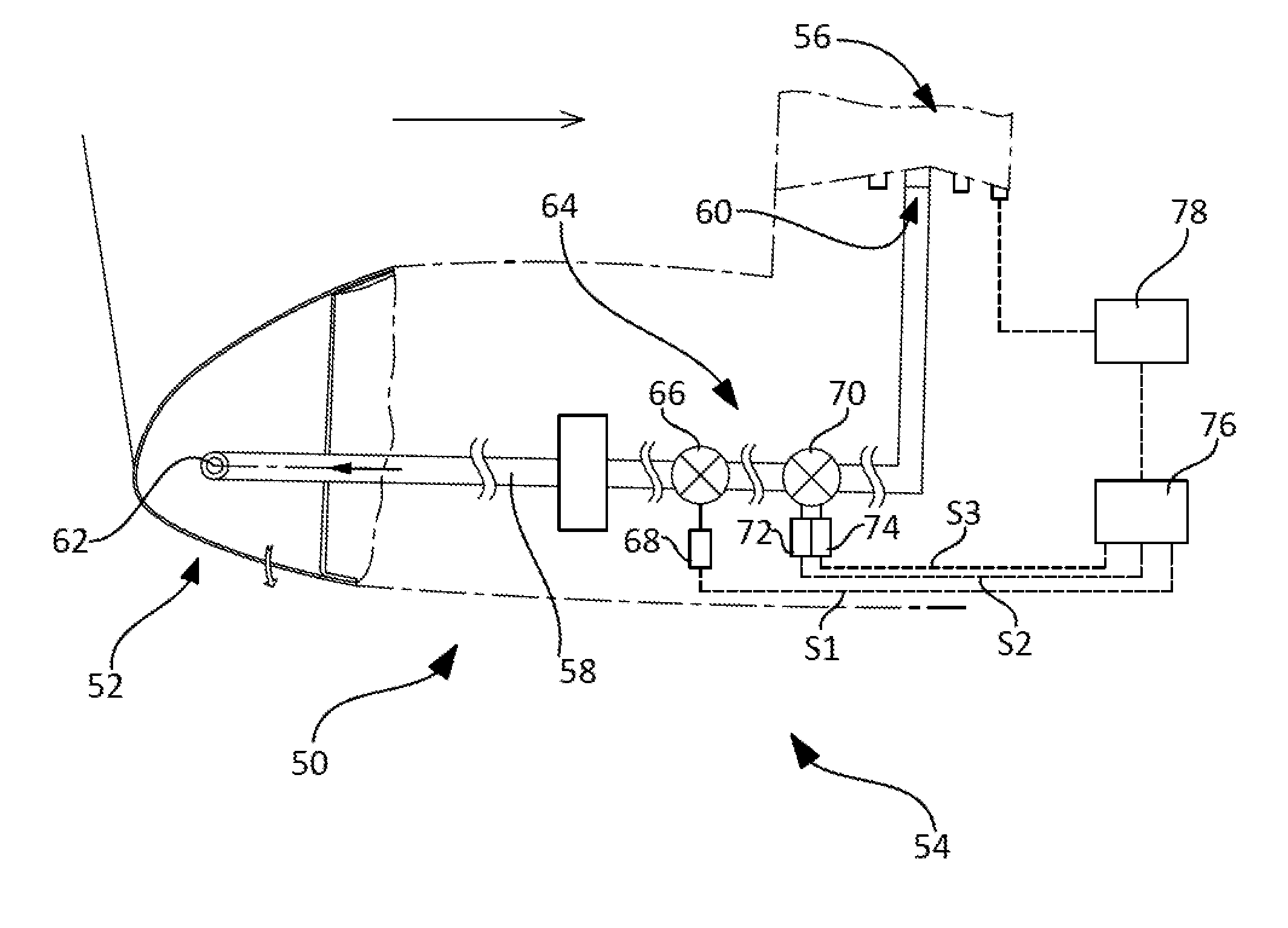
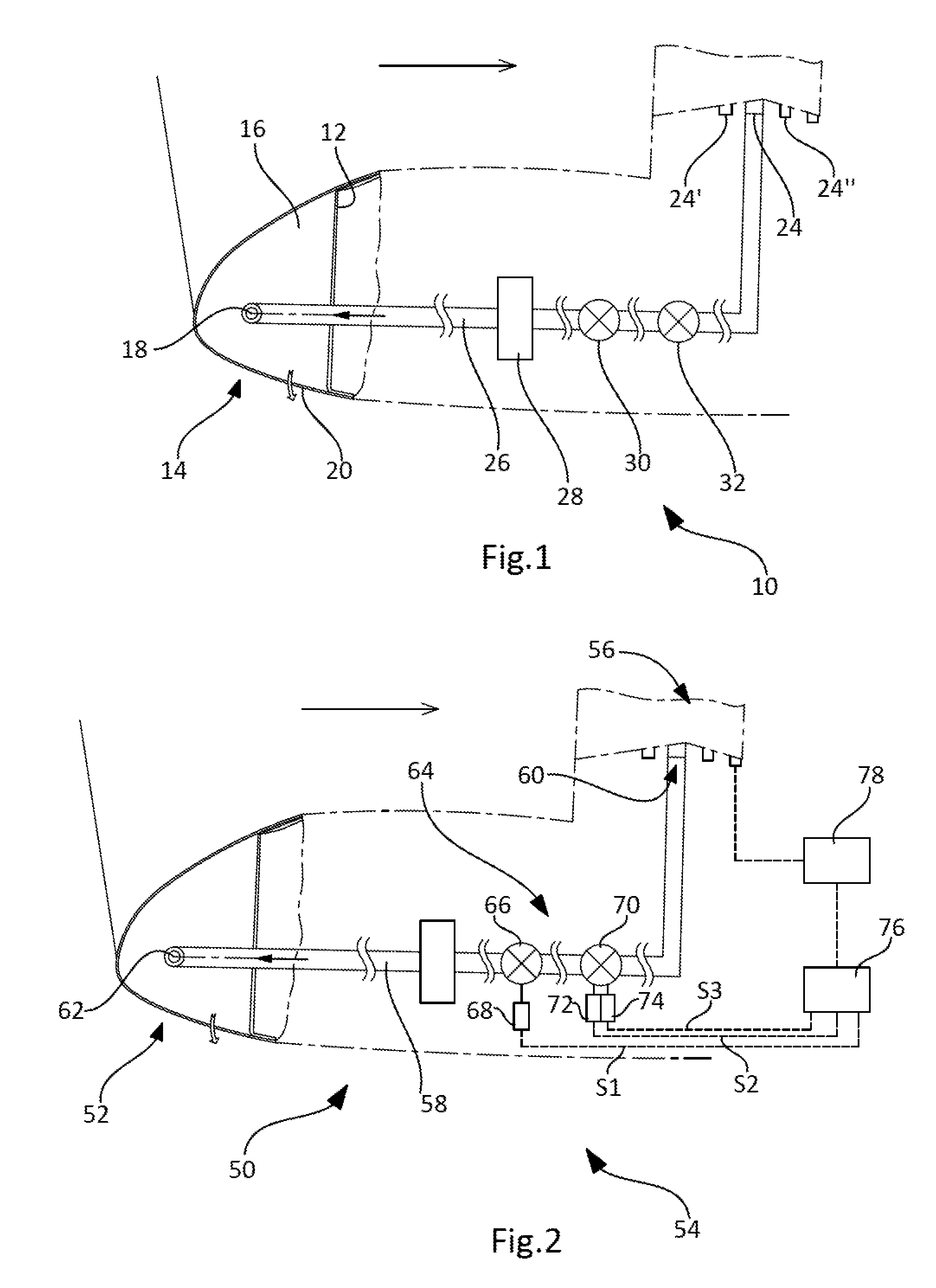
[0041]In FIG. 2 is represented a device 50 for de-icing an air intake 52 of a nacelle 54 of an aircraft in which an engine 56 is located.

[0042]This de-icing device uses hot air and includes a duct 58 for routing a flow of hot air from a hot air source 60 to at least one outlet 62 and a regulator device 64 for controlling the flow of hot air flowing in the duct.

[0043]The outlet 62 and the duct 58 are not described in more detail because they can be identical to those of the prior art.

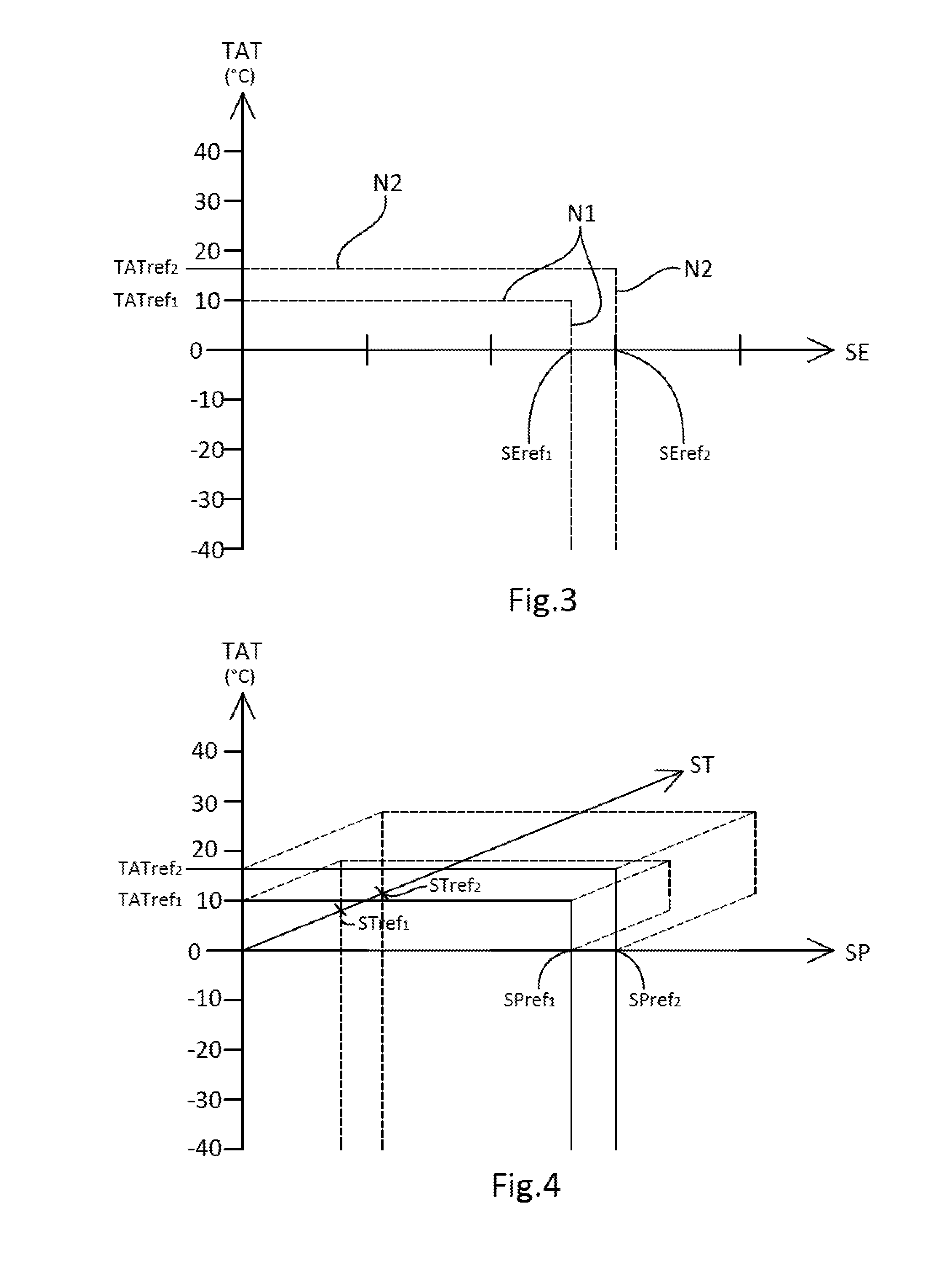
[0044]The hot air supplied by the hot air source 60 is characterized by an energy level SE which is a function notably of the temperature ST and / or the pressure SP of the hot air supplied by the hot air source 60. In accordance with one embodiment, the engine 56 includes a plurality of hot air outlets each with a different temperature / pressure combination. Each hot air outlet can constitute a hot air source 60 for the de-icing device.

[0045]The hot air outlet of the engine is chosen notably as a function ...


PUM


Abstract

A method of regulating the de-icing of a leading edge of an aircraft includes regulating the flow of air used for de-icing by at least a first regulator valve in accordance with two regulation levels, a first regulation level corresponding to the regulated position of the first regulator valve and a second regulation level corresponding to the fully open position of the first regulator valve. A de-icing device enables implementation of the regulation method.

Description

FIELD OF THE INVENTION[0001]The present invention relates to a method for regulating the de-icing of a leading edge of an aircraft and to a device for implementing said method.BACKGROUND OF THE INVENTION[0002]In known manner, a propulsion system of an aircraft includes a nacelle in which an engine is disposed substantially concentrically. The nacelle includes at the front an air intake that is extended inside the nacelle by a duct for channeling the air in the direction of the engine.[0003]Under some conditions, frost or ice may tend to form at the level of the air intake. It is necessary to limit this formation of frost or ice in order to prevent blocks of ice being ingested by the engine and damaging it. To this end, the nacelle includes a de-icing (Nacelle Anti Ice) device. In the remainder of the description, the term de-icing encompasses the treatment of both frost and ice.[0004]The present invention relates more particularly to nacelles incorporating a pneumatic de-icing devic...

Claims


Application Information

Patent Timeline
Patent Type & Authority Applications(United States)
IPC IPC(8): B64D15/04F16K31/12
CPCF16K31/12B64D15/04F02C7/047B64D2033/0233Y02T50/60
Inventor PIRAT, GUILLAUME
Owner AIRBUS OPERATIONS (SAS)
Why Eureka
Try Eureka