Scissor-Type Lift Assembly

a technology of scissor arms and lifts, which is applied in the direction of lifting frames, lifting devices, lifting equipment, etc., can solve the problems of wear to the shaft and the scissor arms, and the wear of the scissor arms, so as to reduce the size of the motor, reduce wear, and reduce wear.

Active Publication Date: 2015-02-05
HERKULES EQUIP
View PDF14 Cites 17 Cited by
  • Summary
  • Abstract
  • Description
  • Claims
  • Application Information

AI Technical Summary

Benefits of technology

[0012]The first and second scissor-type lift assemblies of the lift system include a second retention device coupled to the third end of the second shaft with the second retention device engaging one of the scissor arms of the second and fourth pair of scissor arms. Both of the first and second scissor-type lift assemblies of the lift system include a first brace fixed to another one of the first and third pair of scissor arms with the first brace abutting the first shaft face of the first shaft to maintain alignment of the first shaft along the first and second pivot axes for reducing wear between the first and third pivot axes and the first and third pair of scissor arms. Both of the first and second scissor-type lift assemblies of the lift system include a second brace fixed to another one of the second and fourth pair of scissor arms with the second brace abutting the second shaft face of the second shaft to maintain alignment of the second shaft along the first and second pivot axes for reducing wear between the first and second pivot axes and the second and fourth pair of scissor arms.
[0013]Advantageously, since the first motor of the first scissor-type lift assembly and the second motor of the second scissor-type lift assembly are in communication with and controlled by the controller, the lift system may be precisely controlled. Further, the force is divided between the first and second motors to allow a reduction in motor size. Additionally, since the first and second braces abut the first and second shafts to maintain alignment of the first and second shafts along the first and second pivot axes, wear to the shafts and the pairs of scissor arms is reduced as the pair of scissor arms pivot.

Problems solved by technology

Some lift systems, including the pair of scissor arms, can be susceptible to wear due to flexing and undesired movement of the pair of scissors during operation.
The shaft can flex or move as the pair scissor arms pivot, which can lead to wear to the shaft and the pair of scissor arms.

Method used


Image

  • Scissor-Type Lift Assembly
  • Scissor-Type Lift Assembly
  • Scissor-Type Lift Assembly

Examples


Embodiment Construction

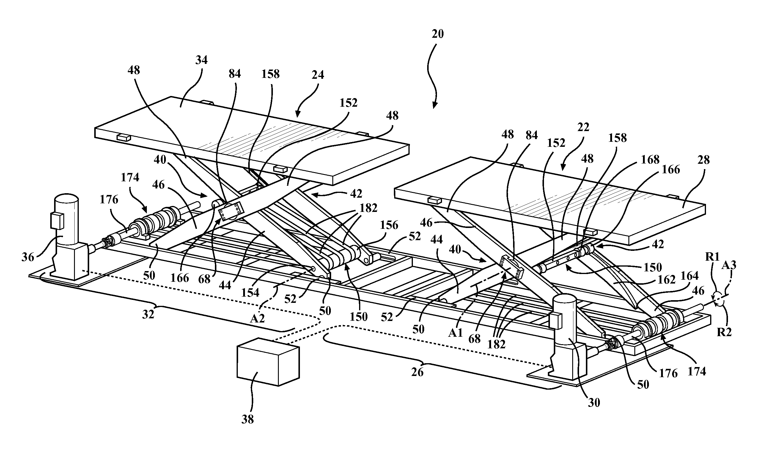
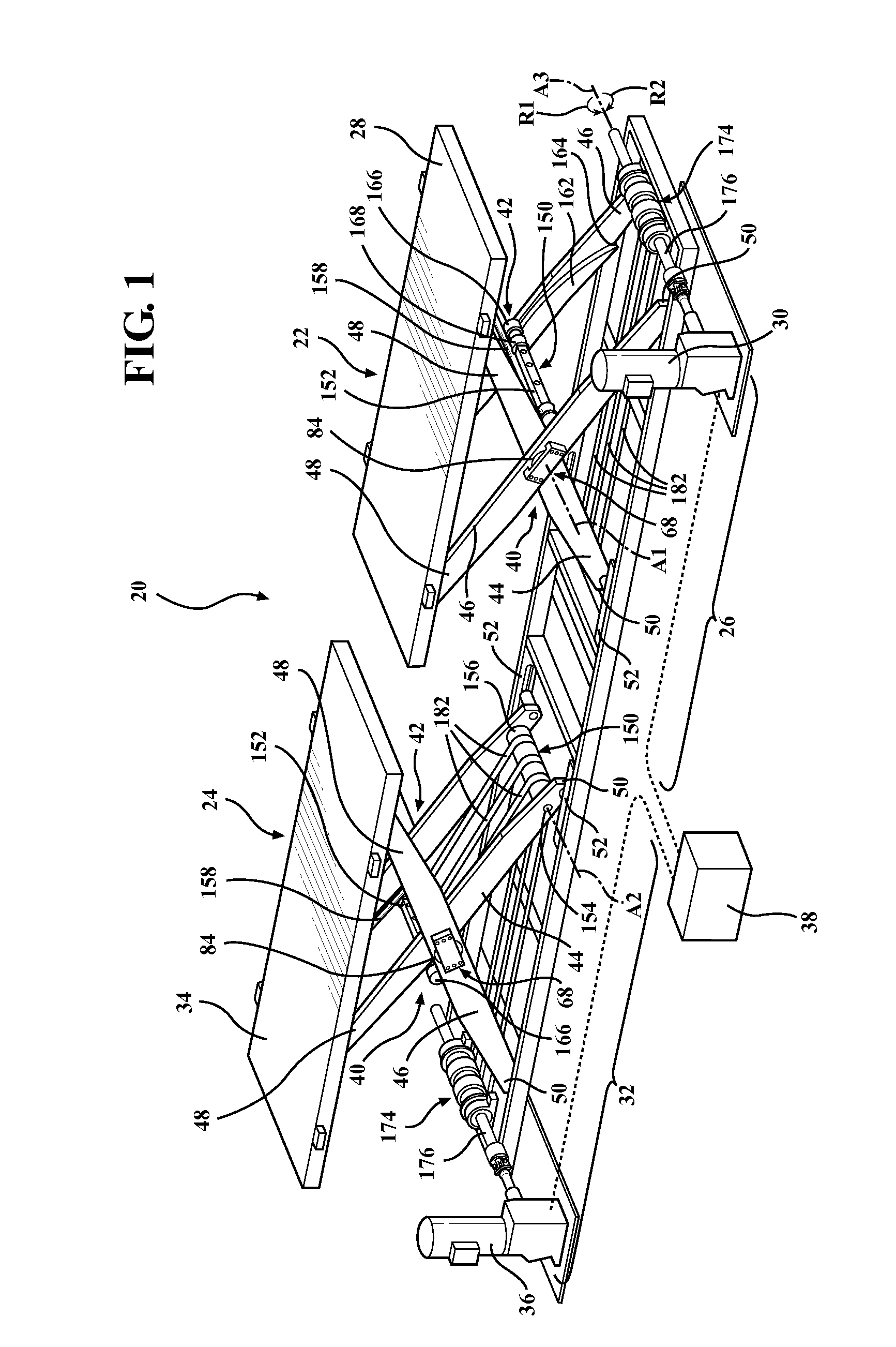
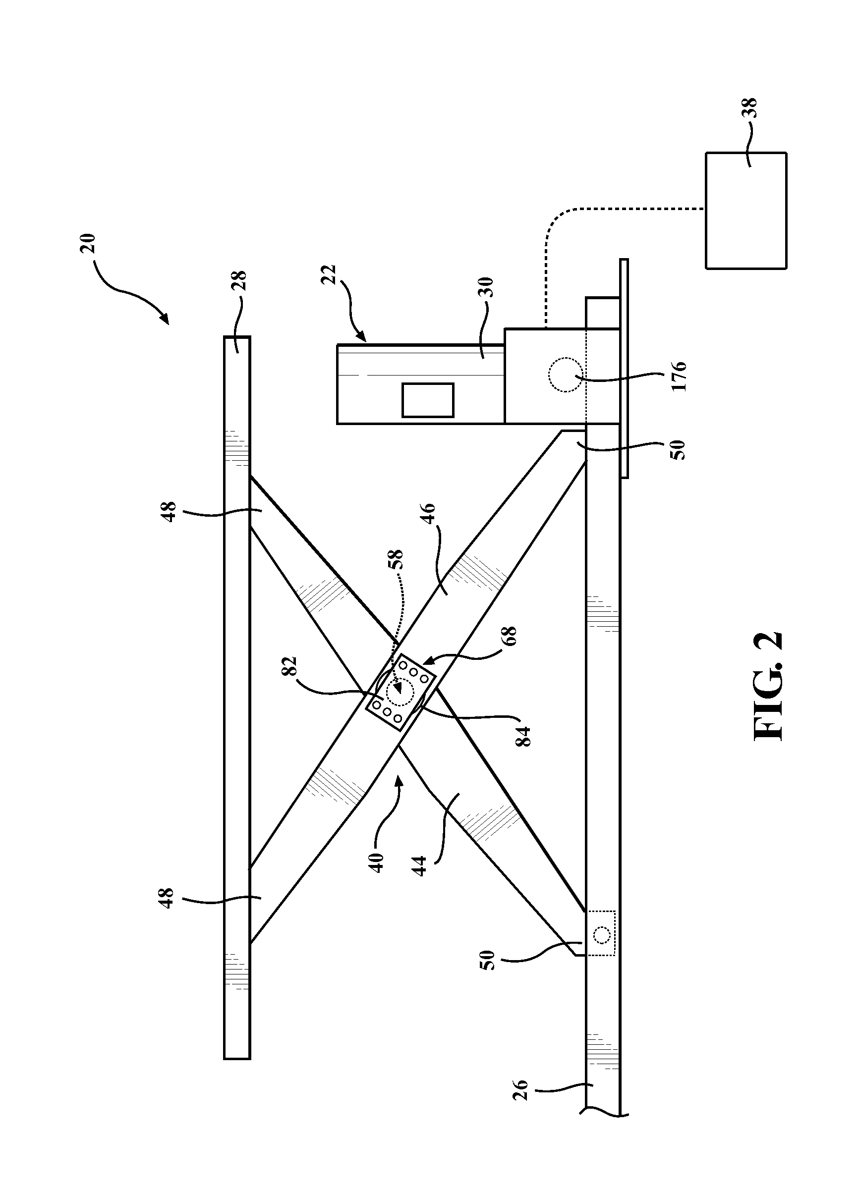
[0029]Referring to the Figures wherein like numerals indicate like or corresponding parts throughout the several views, a lift system 20 including a first scissor-type lift assembly 22 and a second scissor-type lift assembly 24 spaced from the first scissor-type lift assembly 22 is generally shown in FIG. 1.

[0030]The first scissor-type lift assembly 22 includes a first base 26 and a first platform 28 coupled to the first base 26 for movement between elevated and lowered states in which the first platform 28 and the first base 26 are distant and proximate, respectively. The first scissor-type lift assembly 22 includes a first motor 30 mounted to the first base 26 to move the first platform 28 between the elevated and lowered states. The first scissor-type lift assembly 22 is shown in the elevated stated in FIGS. 1 and 2.

[0031]The second scissor-type lift assembly 24 includes a second base 32 and a second platform 34 coupled to the second base 32 for movement between elevated and lowe...


PUM


Abstract

The subject invention includes a lift system including a first scissor-type lift assembly and a second scissor-type lift assembly spaced from the first scissor-type lift assembly. The first scissor-type lift assembly includes a first base and a first platform coupled to the first base for movement between elevated and lowered states. The first scissor-type lift assembly includes a first motor operatively mounted to the first base. The second scissor-type lift assembly includes a second base and a second platform coupled to the second base for movement between elevated and lowered states. The second scissor-type lift assembly includes a second motor operatively mounted to the second base. The first and second motors move the first and second platforms between the elevated and lowered states. The lift system includes a controller in communication with the first and second scissor-type lift assemblies to synchronize operation of the first and second motors.

Description

BACKGROUND OF THE INVENTION[0001]1. Field of the Invention[0002]The present invention generally relates to lift assemblies.[0003]2. Description of Related Art[0004]Transportation systems such as lift systems are well known for moving items or people between two vertically differing locations. Transportation systems such as conveyor assemblies are well known for moving items or people between two horizontally differing locations. It is also known to move the platform or carriage of these systems through a belt-driven apparatus.[0005]One well-known and useful type of lift system is the scissor-type lift assembly, which includes a pair of scissor arms coupled to a platform with the pair of scissor arms pivoting as the platform is moved between an elevated state and a lowered state. Such lift systems are commonly driven through hydraulic cylinders connected to a single hydraulic pump.[0006]Some lift systems, including the pair of scissor arms, can be susceptible to wear due to flexing a...

Claims


Application Information

Patent Timeline
Patent Type & Authority Applications(United States)
IPC IPC(8): B66F7/06B66F3/22B66F7/28B66F3/46
CPCB66F7/0658B66F7/28B66F3/22B66F3/46
Inventor BACON, TODD J.AMUNDSON, ROBERT M.WILHELM, SCOTT F.
Owner HERKULES EQUIP
Why Eureka
Try Eureka