Camera module

a technology of camera module and camera body, applied in the field of camera module, can solve the problems of electromagnetic waves leaked to the outside, communication interference or malfunction, etc., and achieve the effect of increasing the shielding efficiency of electromagnetic waves and preventing the generation of electrical short circuits

a technology of camera module and camera body, applied in the field of camera module, can solve the problems of electromagnetic waves leaked to the outside, communication interference or malfunction, etc., and achieve the effect of increasing the shielding efficiency of electromagnetic waves and preventing the generation of electrical short circuits

US20150037025A1Inactive Publication Date: 2015-02-05SAMSUNG ELECTRO MECHANICS CO LTD

Image

  • Camera module
  • Camera module
  • Camera module

Examples


Embodiment Construction

[0033]Hereinafter, embodiments of the present invention will be described in detail with reference to the accompanying drawings. The invention may, however, be embodied in many different forms and should not be construed as being limited to the embodiments set forth herein. Rather, these embodiments are provided so that this disclosure will be thorough and complete, and will fully convey the scope of the invention to those skilled in the art. In the drawings, the shapes and dimensions of elements may be exaggerated for clarity, and the same reference numerals will be used throughout to designate the same or like elements.

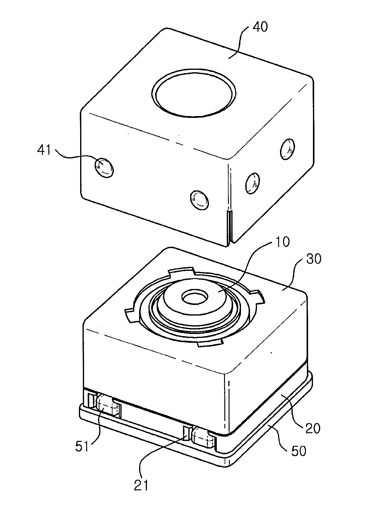
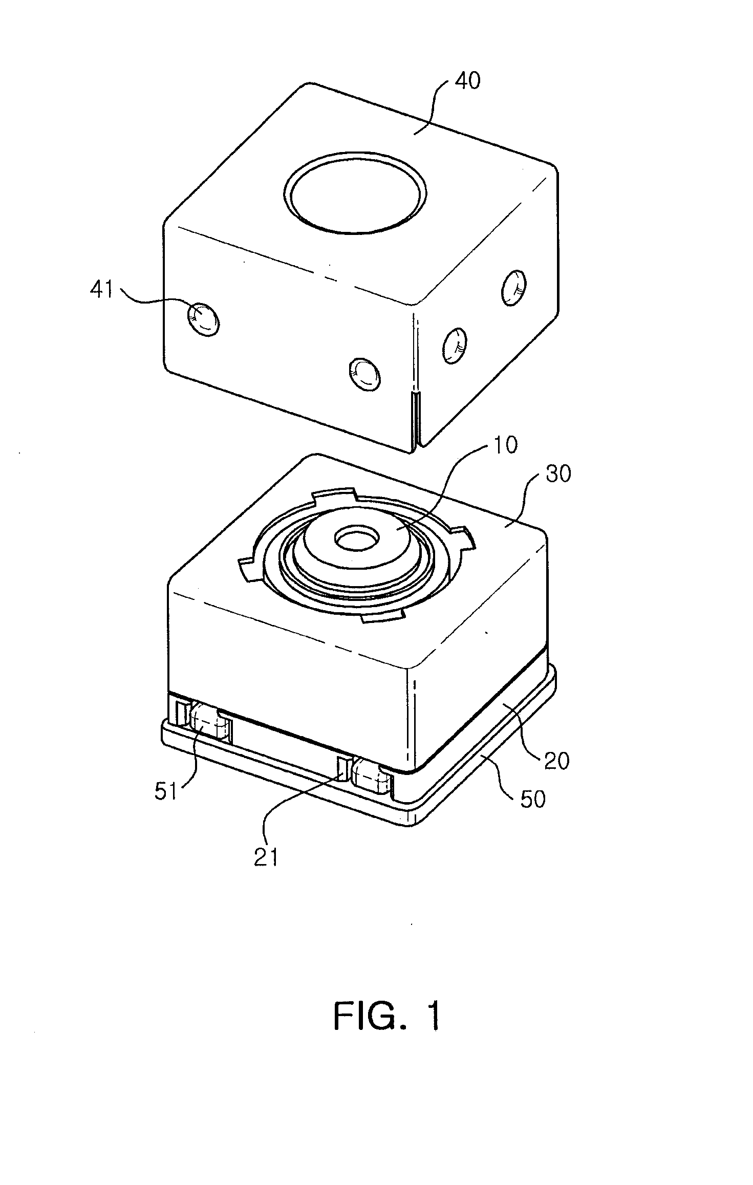
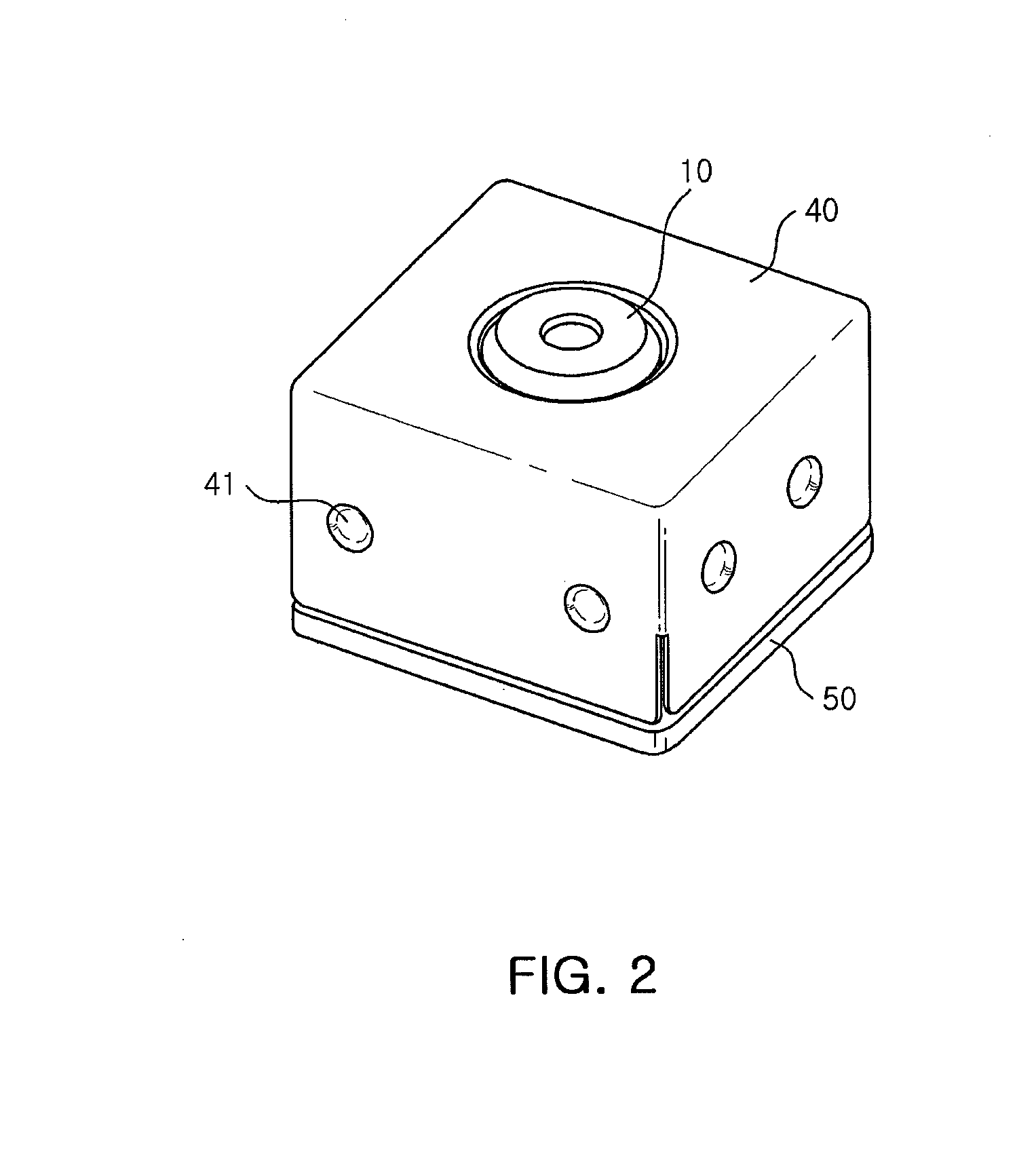
[0034]FIG. 1 is an exploded perspective view of a camera module according to an embodiment of the present invention; and FIG. 2 is an assembled perspective view of the camera module according to the embodiment of the present invention.

[0035]Referring to FIGS. 1 and 2, the camera module according to the embodiment of the present invention may include a lens barrel 10...


PUM


Abstract

There is provided a camera module including: a housing including a lens barrel disposed therein; a first shield can coupled to the housing so that a lower end portion of an outer surface of the housing is exposed; a circuit board mounted at the lower end portion of the housing; and a second shield can covering the first shield can and the lower end portion of the housing, wherein the second shield can is provided with protrusion parts pressing an outer surface of the first shield can.

Description

CROSS-REFERENCE TO RELATED APPLICATIONS[0001]This application claims the priority of Korean Patent Application No. 10-2013-0091942 filed on Aug. 2, 2013, in the Korean Intellectual Property Office, the disclosure of which is incorporated herein by reference.BACKGROUND OF THE INVENTION[0002]1. Field of the Invention[0003]The present invention relates to a camera module.[0004]2. Description of the Related Art[0005]Recently, portable communications terminals such as cellular phones, personal digital assistants (PDA), portable personal computers, and the like, have generally been implemented with the ability to perform the transmission of video data as well as the transmission of text and audio data.[0006]In accordance with this trend, portable communications terminals have been standardly equipped with camera modules have been has been recently installed basically in the in order to enable the transmission of the video data, video chatting, or the like.[0007]Generally, such a camera mo...

Claims


Application Information

Patent Timeline
05 Feb 2015
Publication
US20150037025A1
IPC
G03B17/02
CPC
G03B17/02; H04N23/57; H05K9/00; G03B30/00
Inventors
KIM, JANG HUN; KANG, HWAN JUN