Variable efficiency faraday shield

A variable, efficient technology, applied in the field of electrical shielding, capable of solving problems such as inappropriate

Inactive Publication Date: 2004-06-09
APPLIED MATERIALS INC
View PDF0 Cites 4 Cited by
  • Summary
  • Abstract
  • Description
  • Claims
  • Application Information

AI Technical Summary

Problems solved by technology

However, due to the apparent structural differences, it is inappropriate to use this old terminology to describe at least some embodiments of the present invention

Method used


Image

  • Variable efficiency faraday shield
  • Variable efficiency faraday shield
  • Variable efficiency faraday shield

Examples


Embodiment Construction

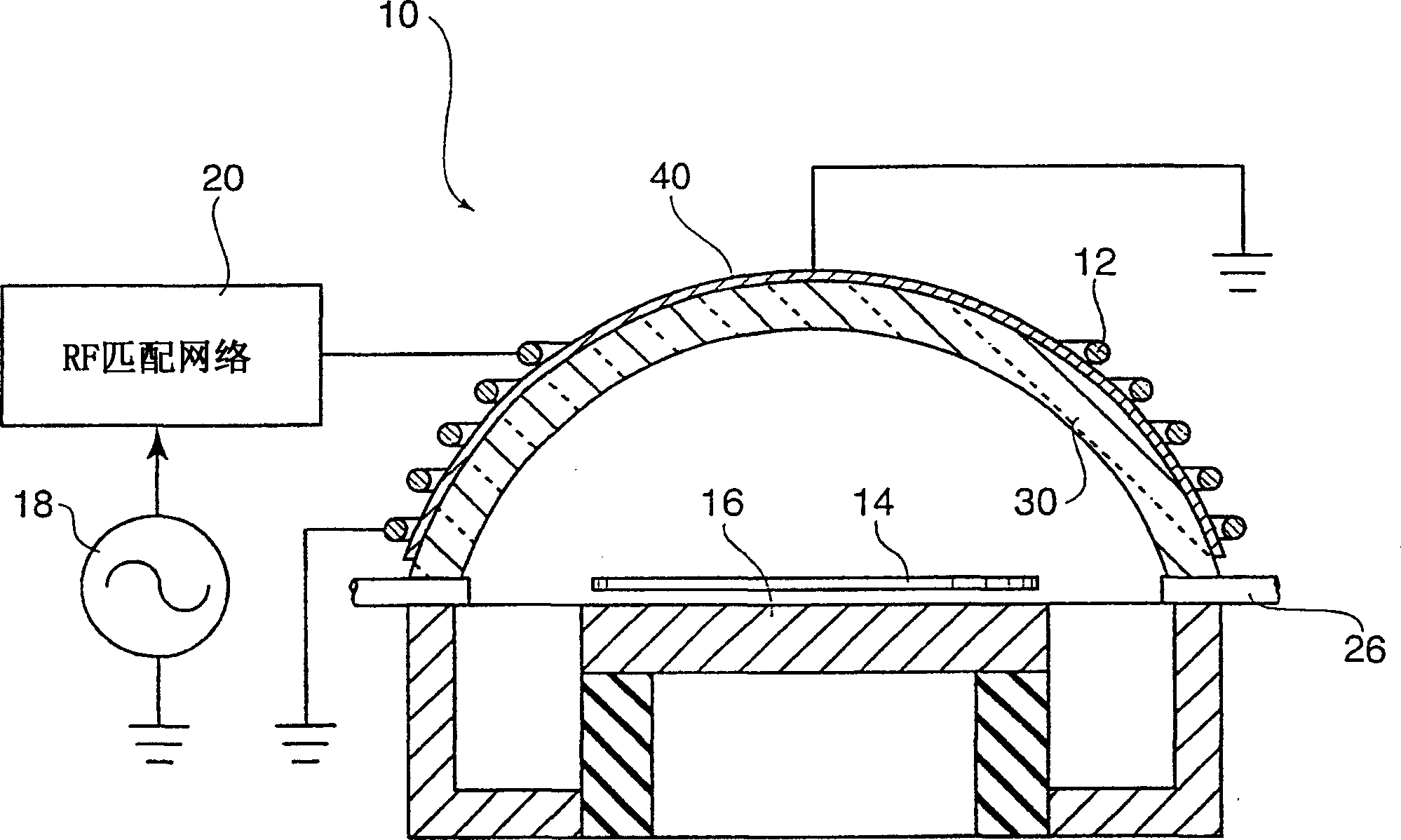
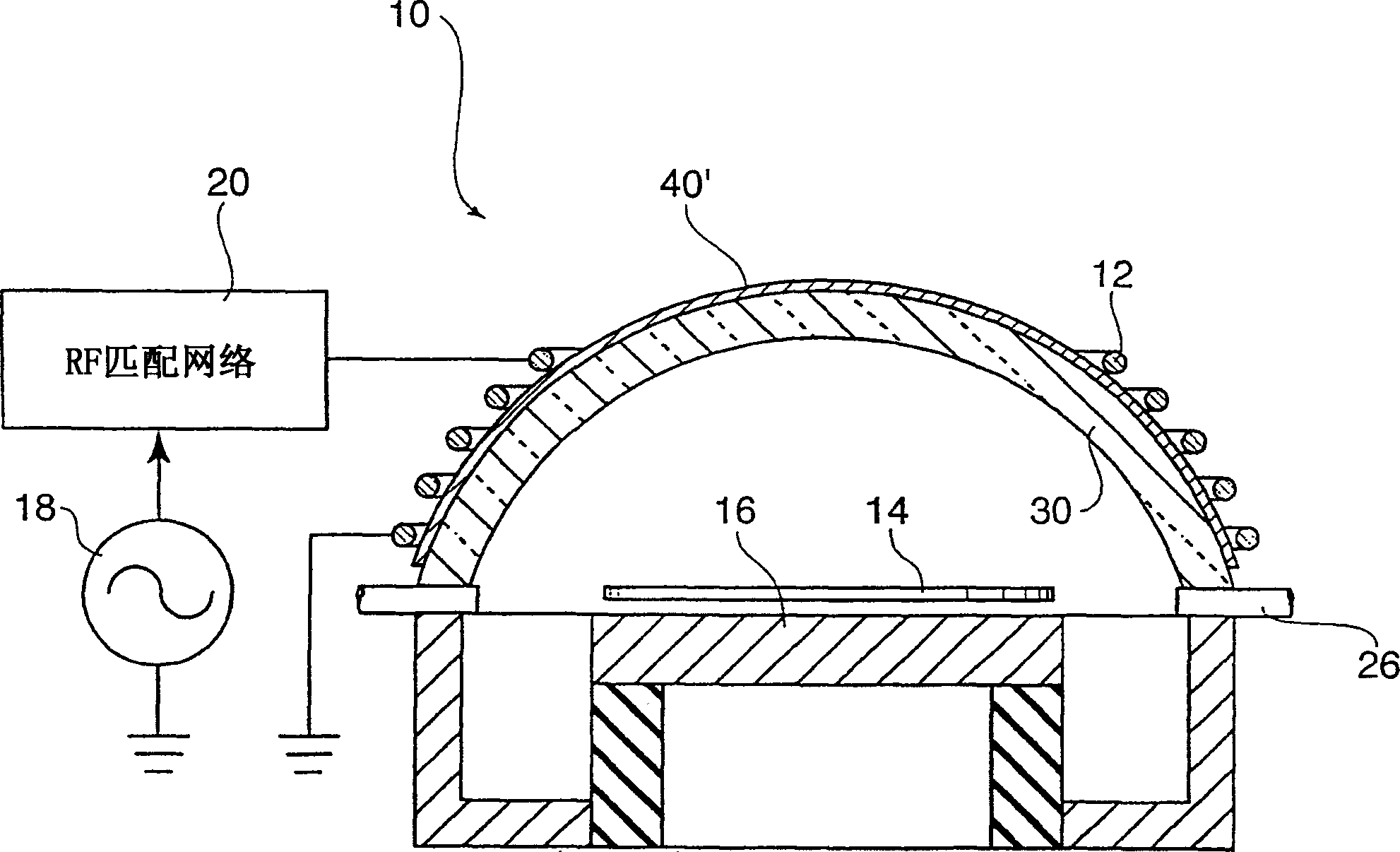
[0040] An ungrounded passive voltage distribution electrode (VDE) is typically placed between the excitation antenna coil and the RF dome in the etch chamber. This VDE is an example of an application specific ungrounded Faraday shield.

[0041] As noted above, grounded shielding is more effective at minimizing capacitive coupling between the excitation antenna and the chamber plasma, and thus reducing the plasma potential difference between the plasma body and the inner surface of the RF aperture. By lowering the plasma potential here, the sputter erosion rate of the ceramic material of the aperture is significantly reduced.

[0042] Unfortunately, the underside of a grounded shield design makes it very difficult to induce a plasma discharge in the chamber and causes the impedance of the focused antenna circuit to drop outside the nominal range of the tuned network. This is the main reason why more effective grounding designs have not been incorporated into prior art plasma c...


PUM


Abstract

A Faraday shield (300) for use with a plasma reactor (930) has a variable shielding efficiency. The shield (300) is divided into numerous shield segments (320) that may each be selectively grounded or ungrounded. The rate of transition between fully ungrounded and fully grounded states is controllable so as to maintain stable plasma conditions in the plasma reactor (930) during the transitional period. The time rate of change of the shielding efficiency can be controlled at a predetermined rate once plasma strike is achieved, or can be made conditional to successful matching at the previous shield setting. When the Faraday shield (300) is fully grounded, the amount of on-wafer and on-chamber contamination is reduced by reducing the rate of sputtering of chamber surfaces.

Description

Background of the invention [0001] The present invention relates generally to the field of electrical shielding. More specifically, the present invention relates to a Faraday shield for a plasma chamber. [0002] Faraday shielding has been used in plasma chambers to reduce capacitive RF coupling that can lead to ion erosion of chamber surfaces. Many chamber materials are prone to ion attack problems: ceramics, quartz, silicon nitride, silicon carbide, plastics, and many others. A Faraday shield is placed between the RF antenna coil and the plasma shielded chamber and reduces the amount of ion erosion of the chamber caused by ion bombardment induced by the RF electric field. This shield can be grounded or floating. [0003] The underside of a grounded shield design makes it very difficult to initiate a plasma discharge in the chamber because reducing capacitive coupling also reduces the magnitude of the RF electric field strength. However ground shielding is effective in re...

Claims


Application Information

Patent Timeline
Patent Type & Authority Applications(China)
IPC IPC(8): H01L21/3065H01J37/32
CPCH01J37/32174H01J37/32082H01J37/321H01L21/3065
Inventor M·F·戴维斯F·胡施达郎
Owner APPLIED MATERIALS INC
Why Eureka
Try Eureka