Magnetic shunt, magnetic shunt arrangement and power device

a magnetic shunt and magnetic shunt technology, applied in the direction of transformer/inductance details, electrical equipment, inductance, etc., can solve the problems of stray magnetic flux, increase in losses, stray magnetic field, etc., and cannot be completely prevented

Inactive Publication Date: 2011-12-08
ABB RES LTD
View PDF0 Cites 4 Cited by
  • Summary
  • Abstract
  • Description
  • Claims
  • Application Information

AI Technical Summary

Problems solved by technology

Stray magnetic fields are therefore not only a technical problem, but also an economic one, since the capitalization values that correspond to the induced load losses represent a significant part of the costs of a power device, such as a power transformer (see R. Komulainen, H. Nordman, “Loss evaluation and the use of magnetic and electromagnetic shields in transformers”, CIGRE International conference on Large and High Voltage Electric Systems, 1988 Session, paper ID: 12-03).
Material reduction may, however, lead to an increase in losses.
In large power devices such as power transformers, the existence of a stray magnetic flux is usually inevitable and cannot be entirely prevented just by care

Method used


Image

  • Magnetic shunt, magnetic shunt arrangement and power device
  • Magnetic shunt, magnetic shunt arrangement and power device
  • Magnetic shunt, magnetic shunt arrangement and power device

Examples


Embodiment Construction

[0042]Exemplary embodiments of the present disclosure provide a magnetic shunt, a magnetic shunt arrangement, and a power device by which magnetic shielding can be efficiently achieved.

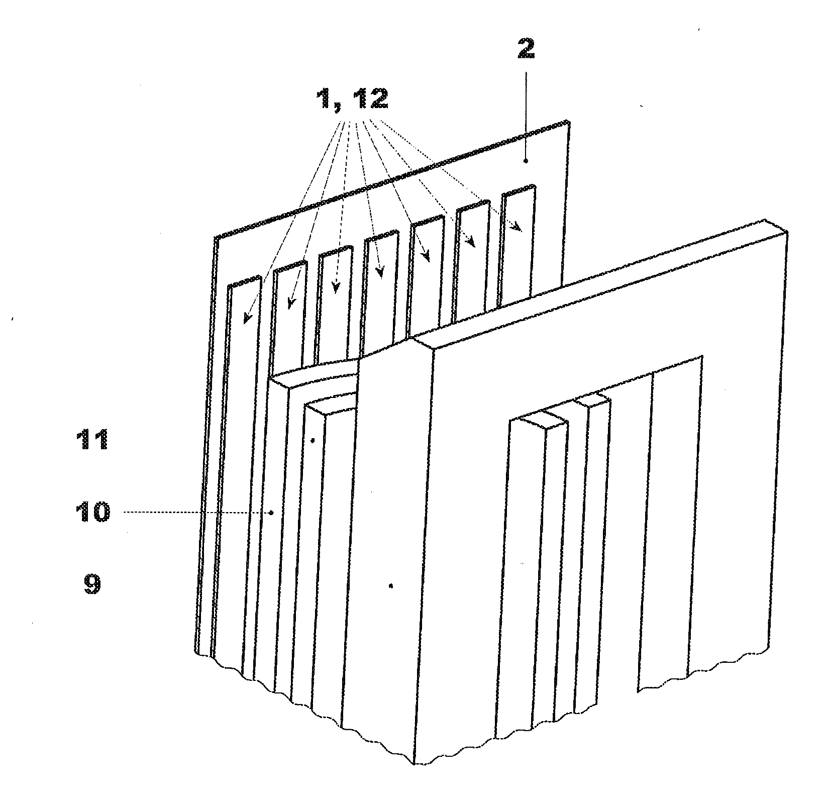
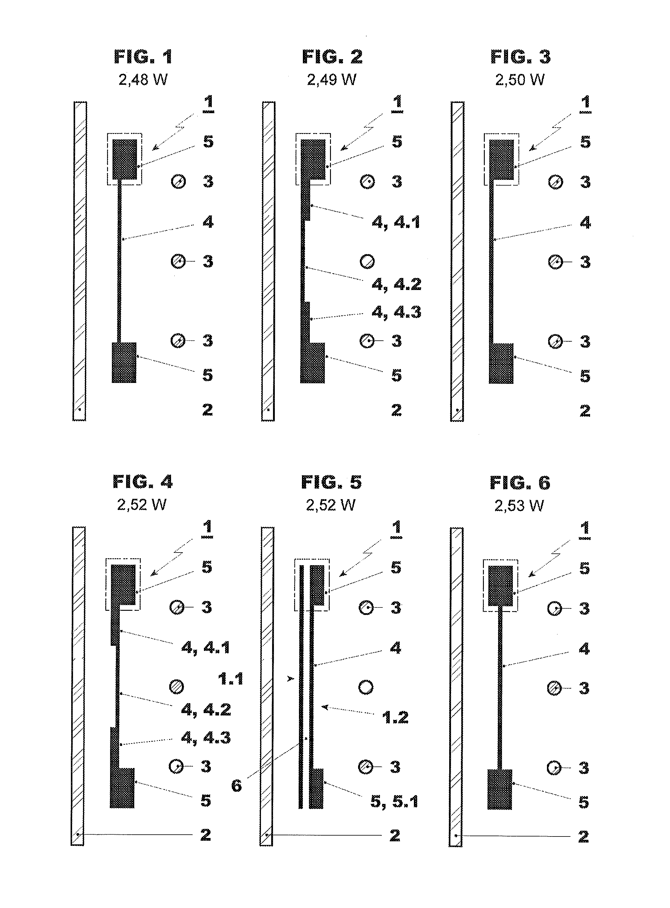
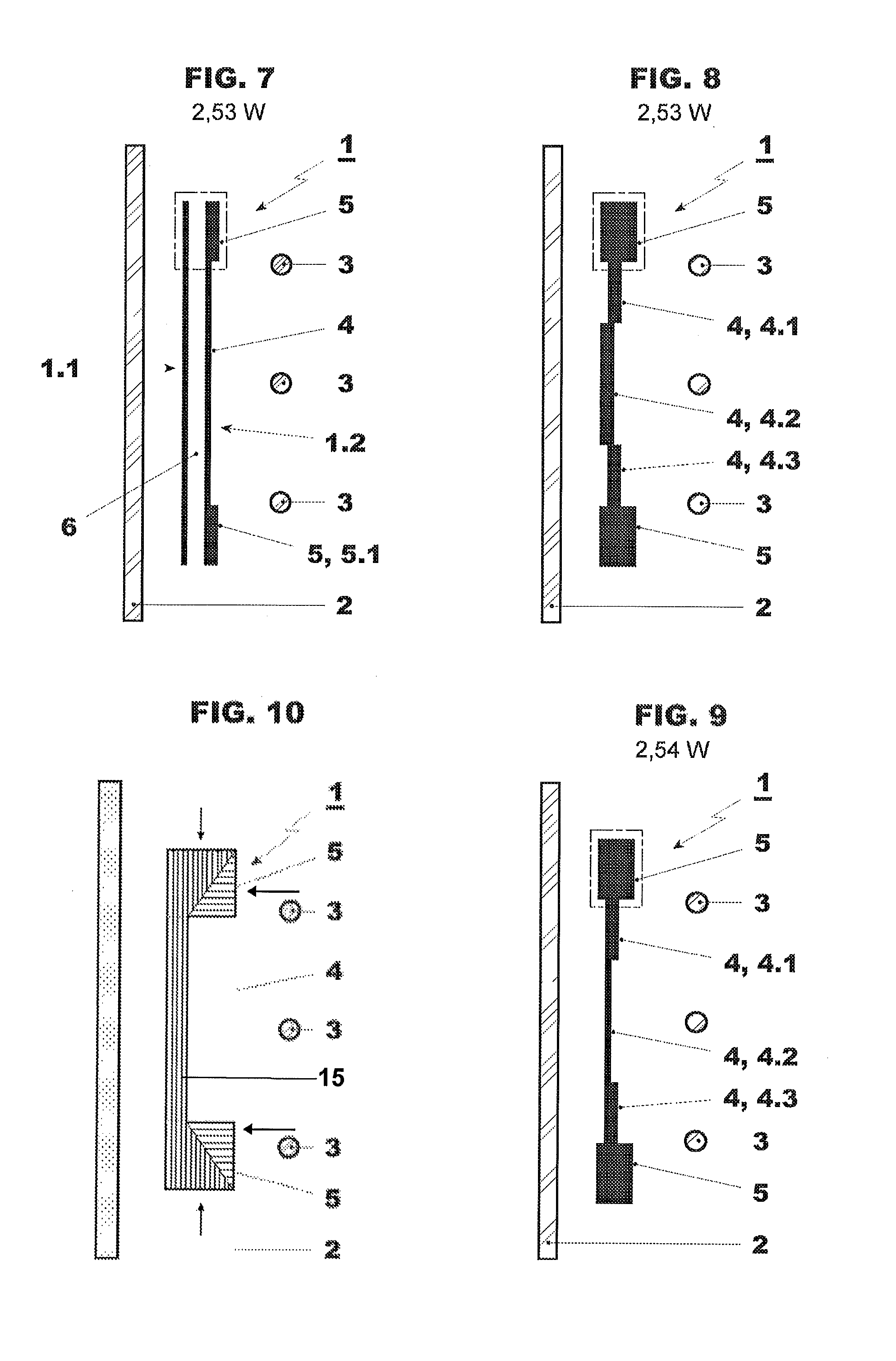
[0043]An exemplary embodiment provides a magnetic shunt for magnetic shielding of a power device (e.g., a power transformer). The magnetic shunt includes magnetic flux collectors that are magnetically connected by a magnetically permeable bridge, wherein the bridge is arranged between the magnetic flux collectors with one magnetic flux collector being placed at each end of the bridge. The cross-section of the magnetic flux collectors is larger than the cross-section of the bridge, and the magnetic shunt forms a single structural unit. The cross-section is defined as a cutting at or about right angles to the longitudinal direction of a magnetic shunt (or a bridge, respectively) when the magnetic shunt is seen in top view.

[0044]Due to its larger cross-section, the magnetic flux collector at one end of t...


PUM


Abstract

A magnetic shunt is provided for magnetic shielding of a power device (e.g., a power transformer). The magnetic shunt includes magnetic flux collectors that are magnetically connected by a magnetically permeable bridge. The bridge is arranged between the magnetic flux collectors with one magnetic flux collector being placed at each end of the bridge. The cross-section of the magnetic flux collectors is larger than the cross-section of the bridge, and the magnetic shunt forms a single structural unit. A magnetic shunt arrangement and a power device which include magnetic shunts according to the present disclosure are also provided.

Description

RELATED APPLICATION[0001]This application claims priority as a continuation application under 35 U.S.C. §120 to PCT / EP 2010 / 0051895. which was filed as an International Application on February 16, 2010 designating the U.S., and which claims priority to European Application 09153106.1 filed in Europe on Feb. 18, 2009. The entire contents of these applications are hereby incorporated by reference in their entireties.FIELD[0002]The present disclosure relates to a magnetic shunt for magnet shielding of a power device, to a magnetic shunt arrangement for magnetic shielding of a power device, and to a power device.BACKGROUND INFORMATION[0003]Magnetic shielding (also called magnetic screening) is employed to protect a certain object that has a certain volume, such as, for example, a power (electrical) device (e.g., a power transformer) from magnetic fields such as, for example, stray magnetic fields. To achieve magnetic shielding / screening, there are currently two known solutions (Ch. Yong...

Claims


Application Information

Patent Timeline
IPC IPC(8): H01F27/36
CPCH01F27/365H01F3/10H01F27/36H01F27/366
Inventor CRANGANU-CRETU, BOGDANSMAJIC, JASMINNORDBORG, HENRIK
Owner ABB RES LTD
Why Eureka
Try Eureka