Magnetic signal measurement apparatus

a technology of magnetic signal and measurement apparatus, which is applied in the direction of magnetic measurement, resistance/reactance/impedence, instruments, etc., can solve the problems of low magnetic shield effect, large opening portions of the cylinder, and the amount of magnetic components perpendicular to the axis of the cylinder, so as to achieve higher shield efficiency, small size, and high shield efficiency

Active Publication Date: 2007-08-21
HITACHI HIGH-TECH CORP
View PDF9 Cites 4 Cited by
  • Summary
  • Abstract
  • Description
  • Claims
  • Application Information

AI Technical Summary

Benefits of technology

[0013]The present invention is capable of structuring a magnetically shielding apparatus that is smaller in the size and higher in the shield efficiency than the conventional apparatus. In particular, (1) because the higher shield efficiency than that of the conventional art is obtained even in the case where the length of the cylinder of the first magnetically shielding apparatus is twice or less as long as the diameter of the opening portion, it is possible to realize the smaller magnetically shielding apparatus. (2) Also, it is possible to reduce an influence of distortion of the signal due to the magnetically shielding apparatus around the magnetic sensor.

Problems solved by technology

(1) Patent Document 1 suffers from such a problem that the magnetic shield effect of a magnetic component in the axial direction of the cylinder is lower than the magnetic shield effect in a direction perpendicular to the axis of the cylinder because both ends of the cylinder are open.
In particular, there arises such a problem that when a length of the cylinder is shorter than twice of a diameter of the opening portion of the cylinder, the amount of magnetic components perpendicular to the axis of the cylinder which enter from the opening portions of the cylinder becomes large, and the magnetic shield effect becomes low.
(2) Also, Patent Document 2 suffers from such a problem that the high permeability material is disposed in the vicinity of a measurement portion, to thereby shield an external magnetic signal, but a measurement signal per se which is an original purpose of the document is distorted.
In particular, because a signal from a sensor that is disposed in the vicinity of the high permeability material is bent toward the high permeability material, there arises such problems that a two-dimensional distribution pattern is changed, or an error occurs in a positional estimate in the case where a magnetic flux density distribution is measured by using a large number of sensors, or in the case where a signal source is estimated from the distribution.
In situation, in the case where a length of the main magnetic shield cylinder is twice or less as long as the diameter of the cylinder, the magnetically shielding apparatus cannot sufficiently shield a component perpendicular to the axis of the cylinder which enters the cylinder from the opening end of the cylinder.

Method used


Image

  • Magnetic signal measurement apparatus
  • Magnetic signal measurement apparatus
  • Magnetic signal measurement apparatus

Examples


first embodiment

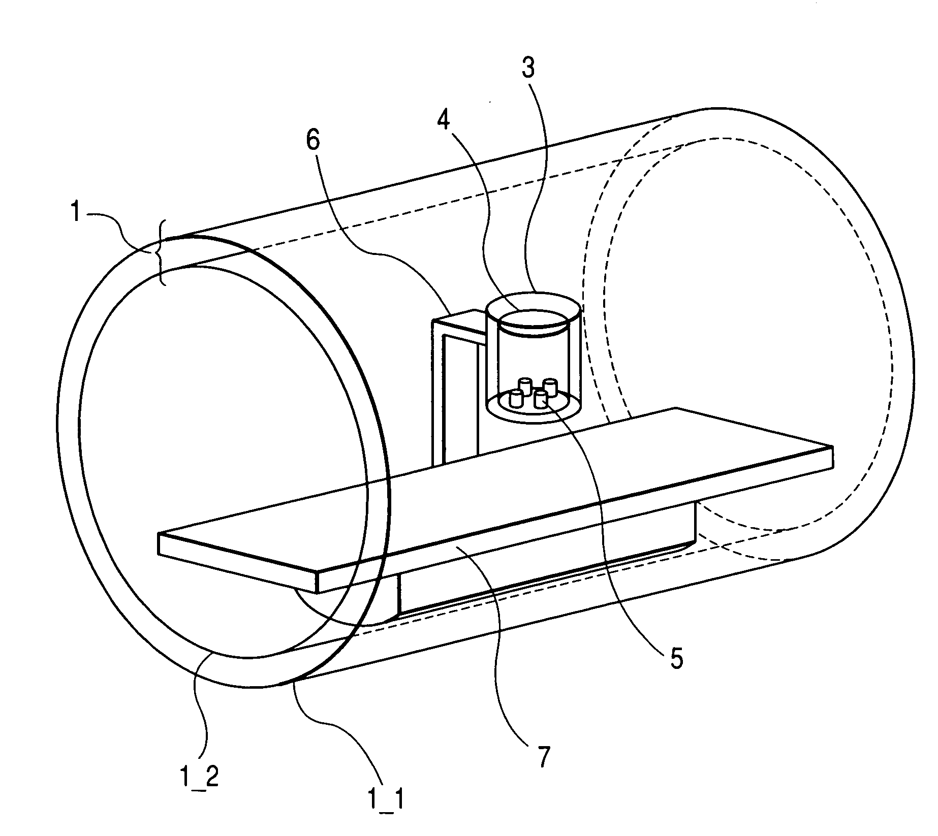
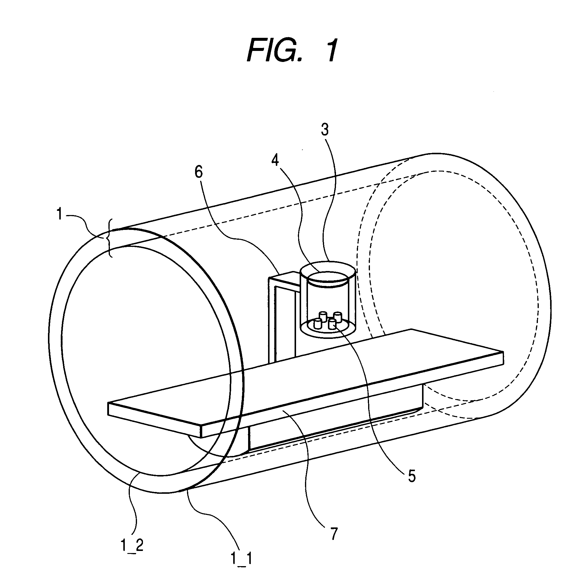
[0027]FIG. 1 shows a perspective view of an embodiment in the case where a first magnetically shielding apparatus 1 is cylindrical, and a biomagnetism, mainly, a magnetic flux density that is generated from a heart is measured. The first magnetically shielding apparatus 1 is made up of a single or plural cylinders which are different in the diameter from each other and have both ends opened. In the first embodiment, the first magnetically shielding apparatus 1 is made up of a first cylinder 1_1 and a second cylinder 1_2. The respective cylinders that constitute the first magnetically shielding apparatus 1 overlap with each other in such a manner that the center axes of the respective cylinders are coaxial with each other. FIG. 1 shows an example in which the number of cylinders that constitute the first magnetically shielding apparatus 1 is two. However, since the magnetic shielding factor is determined according to the thicknesses, the lengths, and the diameters of the respective c...

second embodiment

[0037]FIG. 10 shows a perspective view of another embodiment in the case where a second magnetically shielding apparatus 21 is cylindrical, and a biomagnetism, mainly, a magnetic flux density that is generated from a heart is measured. The first magnetically shielding apparatus 1 is made up of a single or plural cylinders which are different in the diameter from each other and have both ends opened. In the second embodiment, the first magnetically shielding apparatus 1 is made up of a first cylinder 1_1 and a second cylinder 1_2. The respective cylinders that constitute the first magnetically shielding apparatus 1 overlap with each other in such a manner that the center axes of the respective cylinders are coaxial with each other. FIG. 10 shows an example in which the number of cylinders that constitute the first magnetically shielding apparatus 1 is two. However, since the magnetic shielding factor is determined according to the thickness, the length, and the diameter of the respec...

third embodiment

[0039]FIG. 11 shows a case in which a correction region is divided into plural regions, and the correction expression is approximated by a pronominal expression of the distance in the respective regions to conduct the correction. In the drawing, the correction region is divided into three regions. In the numeric correction that is conducted by the acquisition and processing unit 35, the radius dr of the second magnetically shielding apparatus 3 is normalized, and the radius dr is set to 1. The radius dr is divided into three regions which are denoted by dr1 dr2, and dr3 in the order of the cylindrical walls from the center axis of the second magnetically shielding apparatus 3. The correction magnetic flux densities within the respective regions are Bz1, Bz2, and Bz3 in the order of the cylindrical walls from the center axis of the second magnetically shielding apparatus 3. A distance between the center axis 18 of the second magnetically shielding apparatus 3 and the center 5 is ds. ...


PUM


Abstract

As the length of a cylinder of a magnetically shielding apparatus is shorter, the amount of magnetism of a component perpendicular to an axis of the cylinder which enters the opening portion of the cylinder is larger, resulting in a lower magnetic shield effect. A second magnetically shielding apparatus is formed in a cylinder with both ends or one direction close to an object to be measured being opened, and is disposed within a first magnetically shielding apparatus. An axial direction of the cylinder is substantially parallel to the magnetic flux density detection direction. The magnetic sensor, which conducts magnetic signal measurement and is disposed within the cylinder, is in the first magnetically shielding apparatus formed in a cylinder having both open ends, to thereby shield a magnetic flux density component that cannot be shielded by the first magnetically shielding apparatus by the periphery of the magnetic sensor.

Description

CLAIM OF PRIORITY[0001]The present application claims priority from Japanese application JP 2005-170300 filed on Jun. 10, 2005, the content of which is hereby incorporated by reference into this application.FIELD OF THE INVENTION[0002]The present invention relates to a magnetic signal measurement apparatus that measures a faint magnetism or electromagnetic wave signal by using a magnetic sensor or an electromagnetic field sensor.BACKGROUND OF THE INVENTION[0003]As usual, a magnetic shield is realized by perfectly covering an area that is sufficiently larger than a measured area with a high permeability material. However, in this case, in a device that measures magnetism generated from a human body, because a space that is larger than the human body is covered with a high permeability, a large space that is 2 m×2 m×2 m (depth, width, height) is required (for example, Non-Patent Document 1:IEEE Tran. MAG. Vol. MAG-18, No. 1, pp. 260-270, Jan.). A magnetically shielding apparatus obtai...

Claims


Application Information

Patent Timeline
Patent Type & Authority Patents(United States)
IPC IPC(8): G01R27/28
CPCG01R33/0005G01R33/0029G01R33/0047G01R33/025
Inventor SUZUKI, DAISUKE
Owner HITACHI HIGH-TECH CORP
Why Eureka
Try Eureka