Eureka AIR delivers breakthrough ideas for toughest innovation challenges, trusted by R&D personnel around the world.

Controlled nucleation during freezing step of freeze drying cycle using pressure differential water vapor co2 ice crystals

Active Publication Date: 2015-02-12
MILLROCK TECH
View PDF2 Cites 3 Cited by
  • Summary
  • Abstract
  • Description
  • Claims
  • Application Information

AI Technical Summary

Benefits of technology

The new and improved method described in this patent uses CO2 gas as a buffering agent to improve the efficiency of the seeding process. CO2 gas is introduced into the condensing chamber and condensed onto a surface to form a layer of dry ice. This layer helps to break loose the ice crystals during the pressure distribution, improving the yield from frost build up. The CO2 gas also prevents the loss of ice crystals by keeping them frozen and increasing their transfer rate. When the CO2 gas changes state from solid to gas, it absorbs energy and produces additional gas flow, which makes the ice crystals reach their target more efficiently. In summary, this method improves the efficiency and effectiveness of the seeding process.

Problems solved by technology

These compensation methods make the process less efficient in terms of time, material and energy.

Method used


Image

  • Controlled nucleation during freezing step of freeze drying cycle using pressure differential water vapor co2 ice crystals
  • Controlled nucleation during freezing step of freeze drying cycle using pressure differential water vapor co2 ice crystals
  • Controlled nucleation during freezing step of freeze drying cycle using pressure differential water vapor co2 ice crystals

Examples


Embodiment Construction

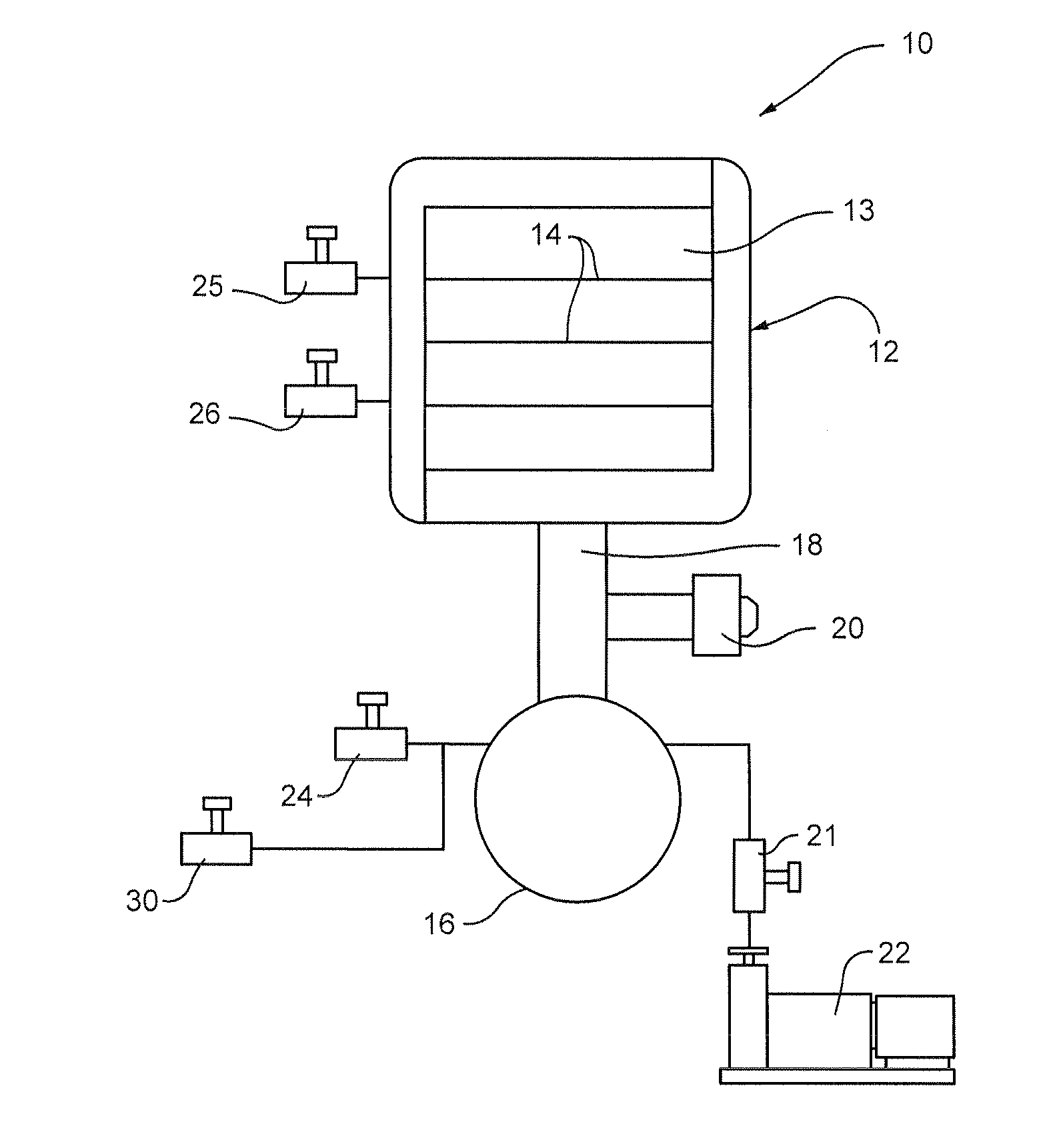
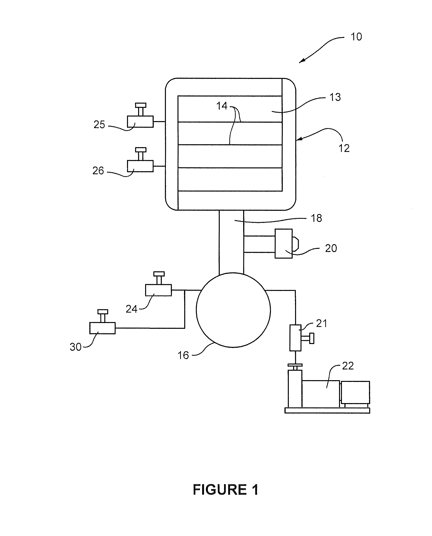
[0013]As shown in FIG. 1, an apparatus 10 for performing the method of the present invention comprises a freeze dryer 12 having one or more shelves 14 for supporting vials of product to be freeze dried. A condenser chamber 16 is connected to the freeze dryer 12 by a vapor port 18 having an isolation valve 20 of any suitable construction between the condenser chamber 16 and the freeze dryer 12. Preferably, the isolation valve 20 is constructed to seal vacuum both ways.

[0014]A vacuum pump 22 is connected to the condenser chamber 16 with a valve 21 therebetween of any suitable construction. The condenser chamber 16 has a release valve 24 of any suitable construction and the freeze dryer 12 has a control valve 25 and release valve 26 of any suitable construction.

As an illustrative example, the operation of the apparatus 10 in accordance with one embodiment of the method of the present invention is as follows:

[0015]1. Cool down the shelf or shelves 14 to a pre-selected temperature (for e...


PUM


Abstract

A method of controlling and enhancing the nucleation of product in a freeze dryer wherein a product is maintained at a predetermined temperature and pressure. A mixture of water vapor and CO2 gas is introduced into a condenser chamber separate from the product chamber to create a predetermined volume of condensed frost, ice and dry ice crystals on an inner surface of the condenser chamber. The condenser chamber is connected to the product chamber and has a predetermined pressure that is greater than that of the product chamber. Upon the opening of the condenser chamber into the product chamber, gas turbulence is created that causes the condensed frost in the form of an ice fog and accompanying ice and dry ice crystals to rapidly enter the product chamber for even distribution therein to create uniform and rapid nucleation of the product in different areas of the product chamber.

Description

BACKGROUND OF THE INVENTION[0001]1. Field of the Invention[0002]The present invention relates to a method of controlling nucleation during the freezing step of a freeze drying cycle and, more particularly, to such a method that uses a pressure differential water vapor and CO2 ice fog and ice crystal distribution to trigger a spontaneous nucleation among all vials in a freeze drying apparatus and to minimize melting of ice crystals during flow from the condenser chamber to the product to be freeze dried.[0003]2. Description of the Background Art[0004]As described in my copending application Ser. No. 13 / 097,219, filed on Apr. 29, 2011, the new and improved controlled ice nucleation method utilizes the pressure differential between the seeding chamber (condensing chamber) and product chamber in a freeze dryer to instantly distribute the ice nucleation seeding crystals across the whole batch of product. Seeding ice crystals are originally generated inside a cold condensing chamber typic...

Claims


Application Information

Patent Timeline
IPC IPC(8): F26B5/06
CPCF26B5/06
Inventor LING, WEIJIA
Owner MILLROCK TECH
Why Eureka
Eureka Blog
Learn More