Fuel igniter assembly having heat-dissipating element and methods of using same

a technology of heat dissipation element and fuel igniter, which is applied in the ignition of turbine/propulsion engines, sparking plugs, lighting and heating apparatus, etc., can solve the problems of fatigue, reduced lifetime, and more susceptible components of fuel igniters

Active Publication Date: 2015-02-12
UNISON INDUSTRIES
View PDF39 Cites 28 Cited by
  • Summary
  • Abstract
  • Description
  • Claims
  • Application Information

AI Technical Summary

Problems solved by technology

As operating voltages of fuel igniters and the operating temperatures of gas turbine engines increase, components housed within the fuel igniter become more susceptible to overheating, fatigue, and decreased lifetime caused by such overheating and fatigue.

Method used


Image

  • Fuel igniter assembly having heat-dissipating element and methods of using same
  • Fuel igniter assembly having heat-dissipating element and methods of using same
  • Fuel igniter assembly having heat-dissipating element and methods of using same

Examples


Embodiment Construction

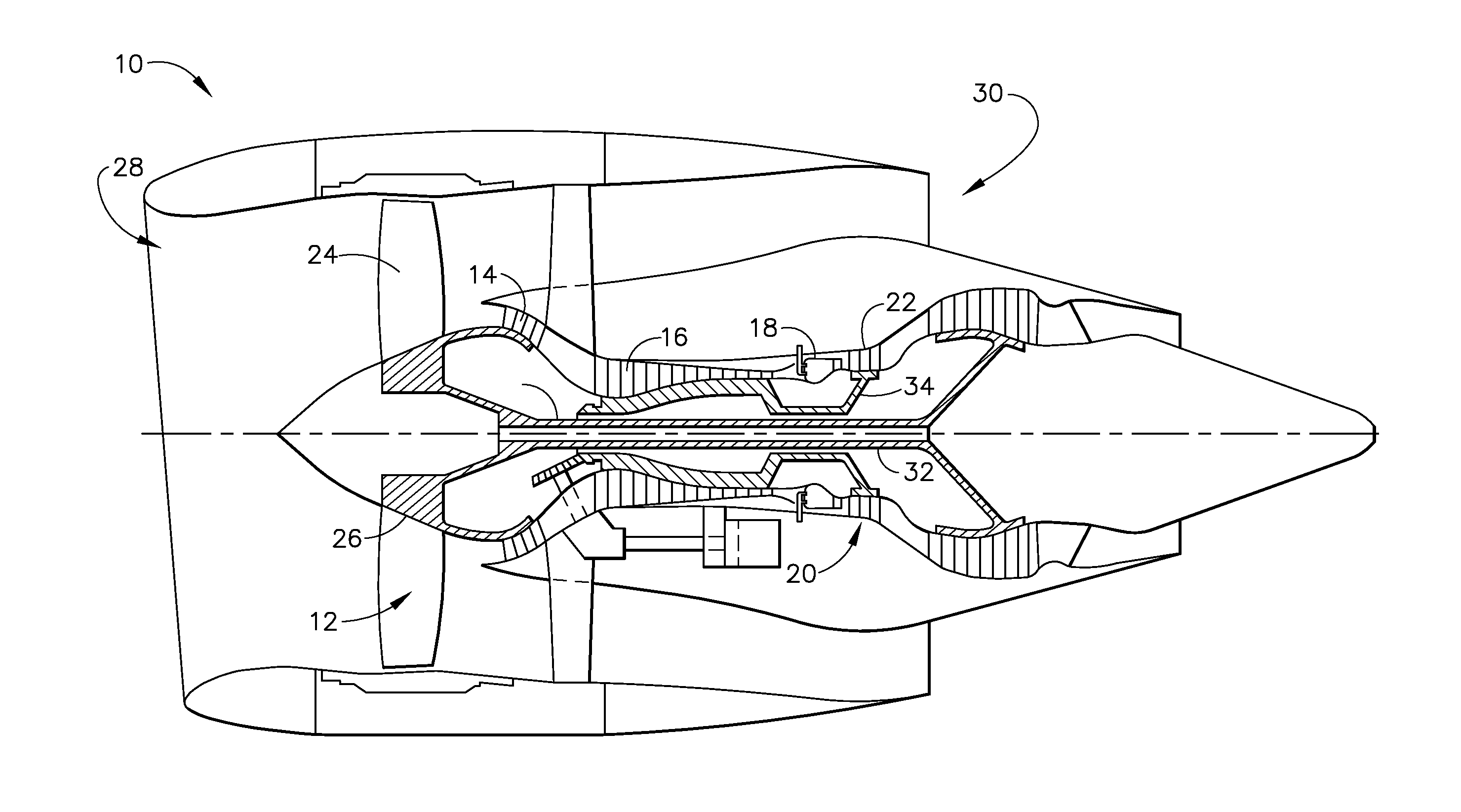
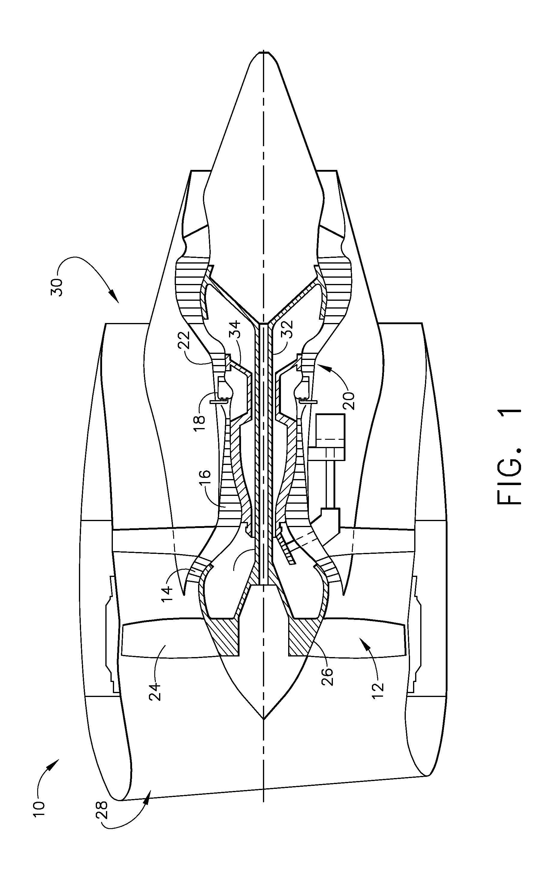
[0015]The following detailed description sets forth fuel igniter assemblies and methods of using the fuel igniter assemblies by way of example and not by way of limitation. The description should clearly enable one of ordinary skill in the art to make and use the fuel igniter assemblies, and the description sets forth several embodiments, adaptations, variations, alternatives, and uses of the fuel igniter assemblies, including what is presently believed to be the best mode thereof The fuel igniter assemblies are described herein as being applied to a preferred embodiment, namely as a high-voltage fuel igniter assembly for a gas turbine engine or a steam turbine. However, it is contemplated that the fuel igniter assemblies and the methods of using the same may have general application in a broad range of systems other than gas turbine engines (e.g., automobiles, watercraft, spacecraft, etc.) and / or a variety of commercial, industrial, and / or consumer applications other than as a high...


PUM


Abstract

A combustor for a gas turbine engine includes a combustion chamber and a fuel igniter assembly. The combustion chamber is defined by an annular inner combustor liner and an annular outer combustor liner. The fuel igniter assembly is coupled to the combustor and extends radially outward from the outer combustor liner. The fuel igniter assembly includes an igniter housing configured to house a fuel igniter therein, and a heat-dissipating element coupled to the igniter housing. The heat-dissipating element includes a plurality of fins configured to dissipate heat from the fuel igniter assembly.

Description

BACKGROUND OF THE DISCLOSURE[0001]The application described herein relates generally to gas turbine engine components, and more specifically to fuel igniter assemblies having heat-dissipating elements.[0002]Gas turbine engines typically include a combustor for combusting an air-fuel mixture to produce energy and drive turbines within the gas turbine engine. A fuel igniter is typically provided to ignite the air-fuel mixture within a combustion chamber of the combustor. Heat generated by the combustion of such air-fuel mixtures is conducted through the fuel-igniter, which is typically housed within a metal casing.[0003]As operating voltages of fuel igniters and the operating temperatures of gas turbine engines increase, components housed within the fuel igniter become more susceptible to overheating, fatigue, and decreased lifetime caused by such overheating and fatigue.[0004]Accordingly, a need exists for a fuel igniter assembly having enhanced heat dissipation properties as compare...

Claims


Application Information

Patent Timeline
Patent Type & Authority Applications(United States)
IPC IPC(8): F02C7/264F02C7/266H01T13/20F23R3/00
CPCF02C7/264F23R3/005H01T13/20F02C7/266F23R3/002F05D2260/20F23Q3/006H01T13/16H01T13/52
Inventor MARTINEZ FABRE, RAUL ARROYOMARTINEZ CERVANTES, JUAN HUMBERTOGUTIERREZ ESPINOSA, RICARDO ARTUROBENKABBOU, HICHAM
Owner UNISON INDUSTRIES
Why Eureka
Try Eureka