
Emergency stop method for hybrid construction equipment and brake control device

a technology of hybrid construction and emergency stop, which is applied in the direction of dynamo-electric converter control, motor/generator/converter stopper, braking system, etc., can solve the problems of large increase in the risk of an accident, damage to the peripheral area of the work environment, etc., and achieves stable stopping of the swing body, rapid response, and reduced impact to the user at the time of braking

Active Publication Date: 2015-02-12
DOOSAN INFRACORE CO LTD
View PDF7 Cites 7 Cited by
  • Summary
  • Abstract
  • Description
  • Claims
  • Application Information

AI Technical Summary

Benefits of technology

The present disclosure provides an emergency stop method for hybrid construction equipment that can quickly and safely stop the swing body in case of an emergency situation. This method uses multiple functions to confirm the failure location and absorb the inertial energy of the swing body, reducing impact and risk of injury to users and reducing the risk of braking or turning over construction equipment on a slope.

Problems solved by technology

As described above, in the hybrid excavator, the upper swing body is freely rotated before a braking operation when the electric power conversion device is stopped, unlike a hydraulic excavator, and thus there is a problem in that a risk of an accident is greatly increased in this case.
When the swing body is continuously rotated, there is a problem in that a peripheral area of the work environment may be damaged.
In this case, there is a problem in that when the braking operation is immediately performed using a mechanical swing brake in a case in which a large amount of inertial energy remains because a speed of the swing body is high immediately before failure occurs, impact may be applied to a user, and the excavator may be turned over on a slope.

Method used


Image

  • Emergency stop method for hybrid construction equipment and brake control device
  • Emergency stop method for hybrid construction equipment and brake control device
  • Emergency stop method for hybrid construction equipment and brake control device

Examples


Embodiment Construction

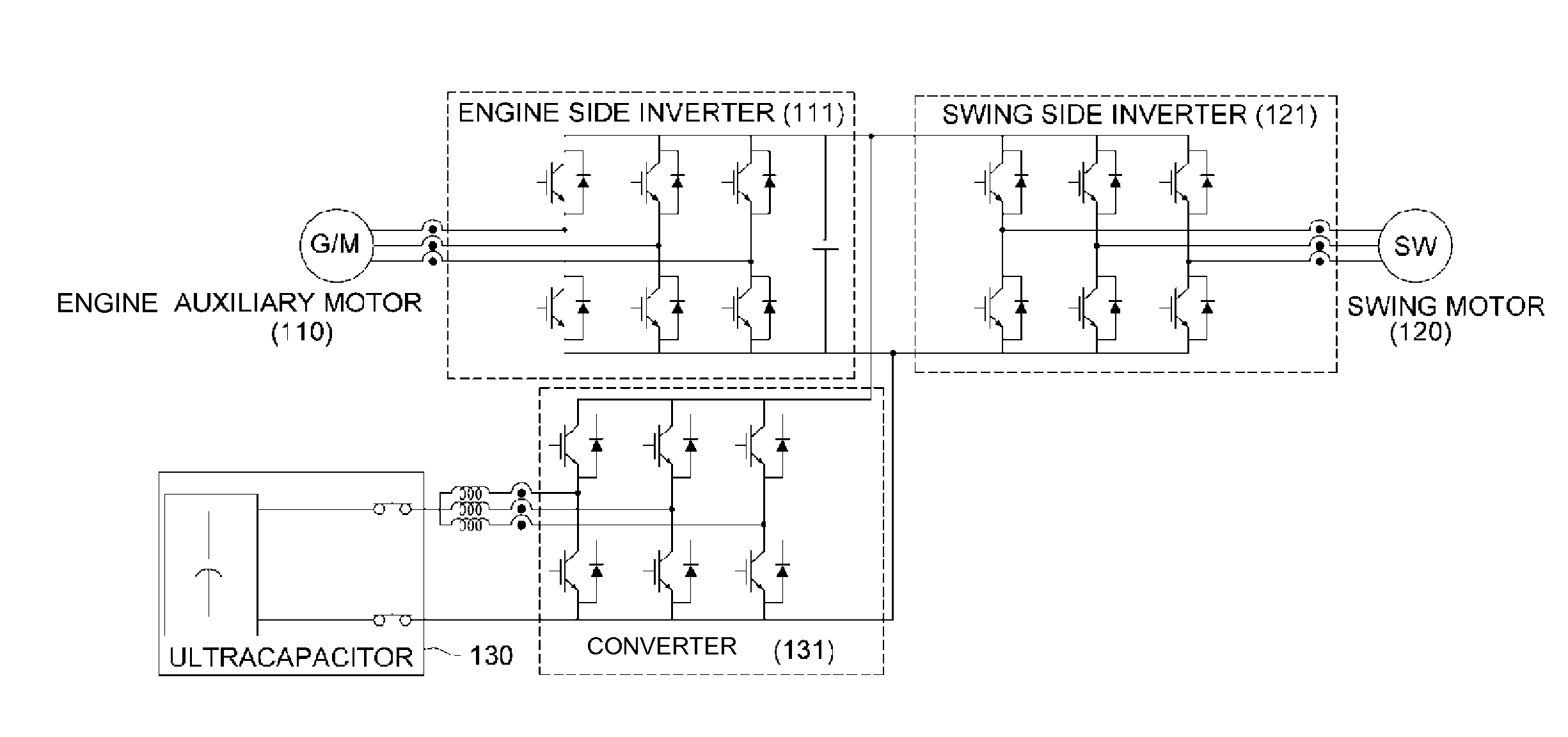
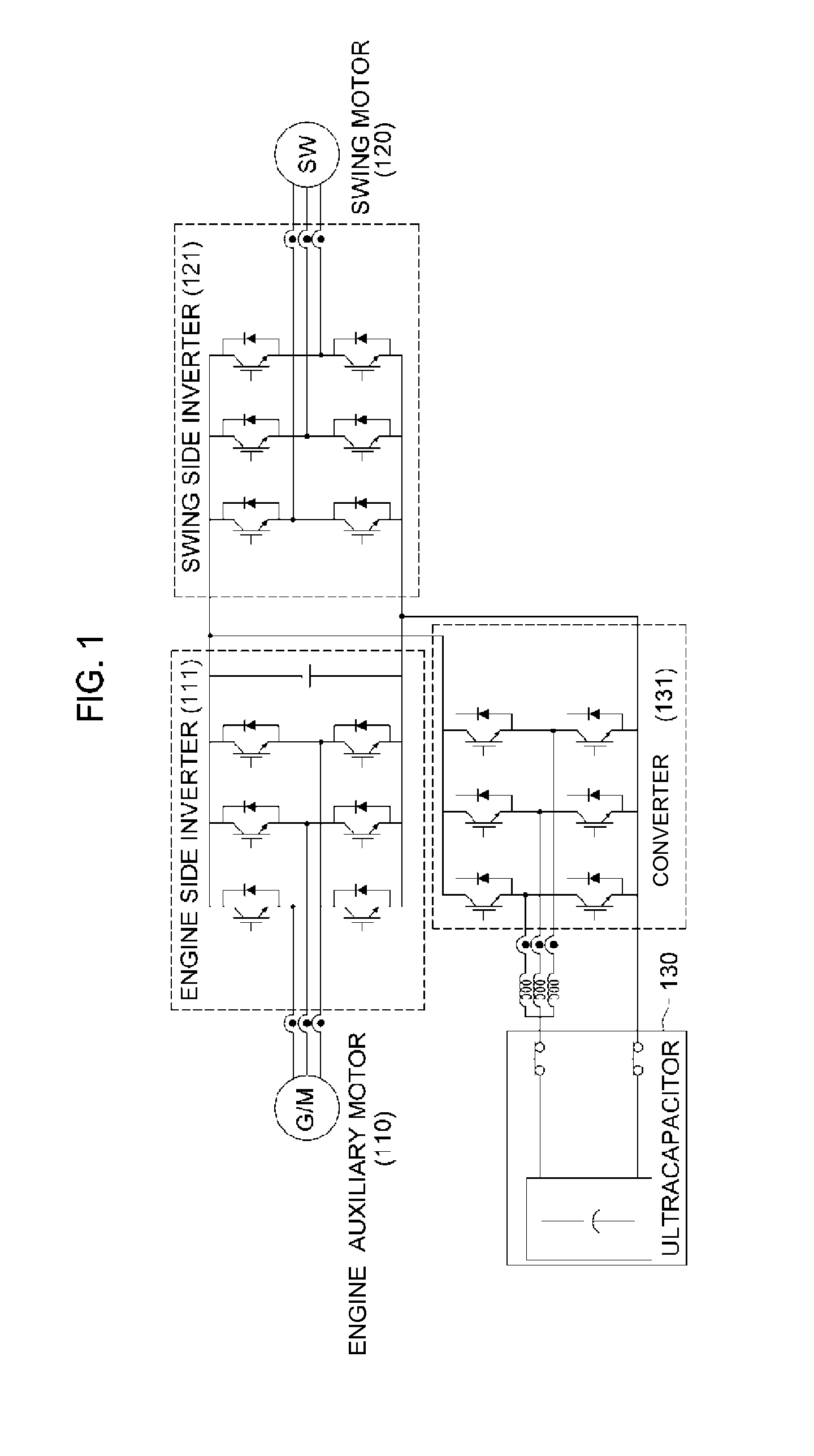
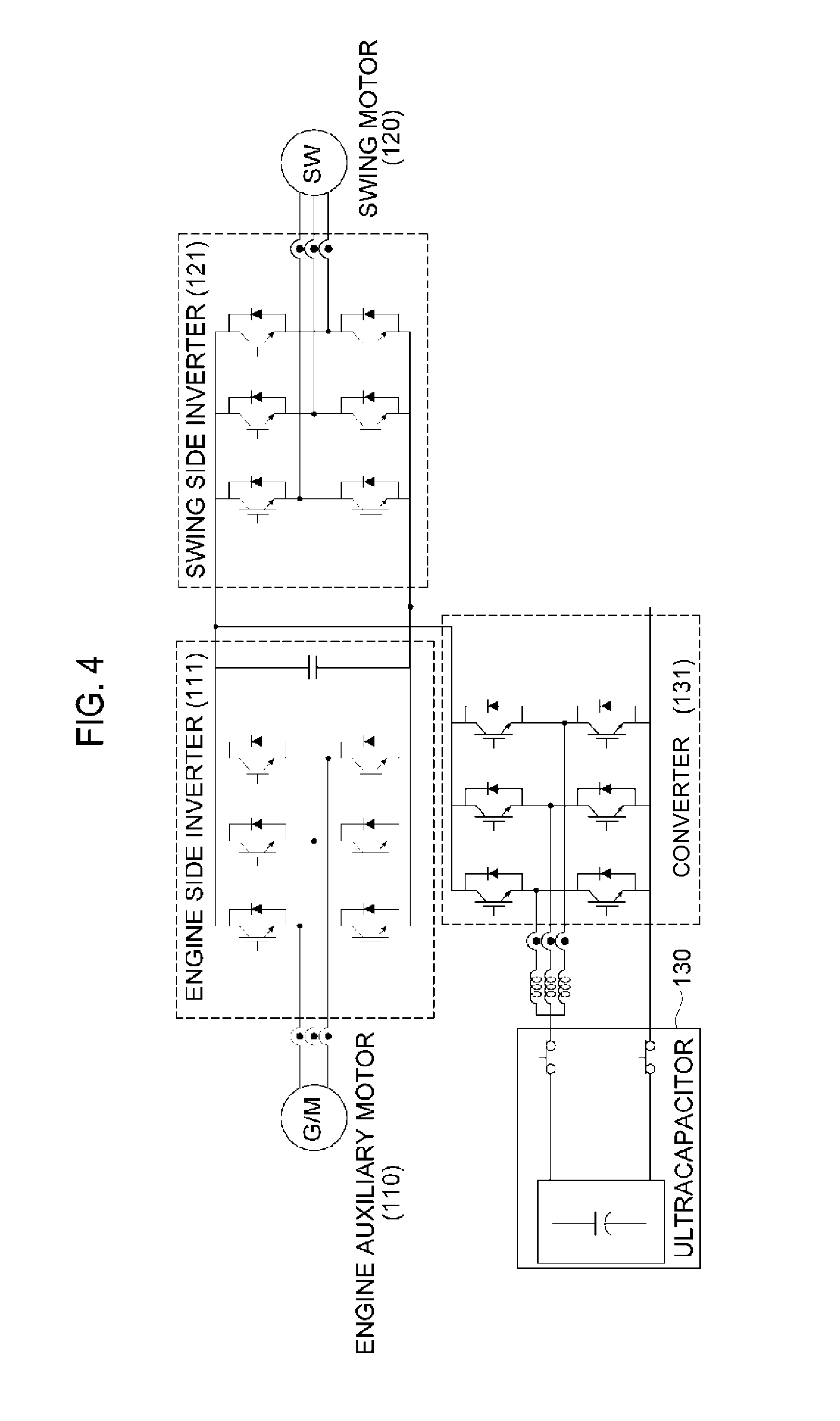
[0055]Hereinafter, an exemplary embodiment according to the present disclosure will be described in detail with reference to the accompanying drawings. A configuration of the present disclosure and an operation and an effect according to the configuration of the present disclosure will be clearly understood by the detailed description below. In the following detailed description, it should be noted that the same elements will be designated by the same reference numerals even though the elements are illustrated in different drawings, and a detailed explanation of publicly known related configurations may be omitted so as to avoid unnecessarily obscuring the subject matter of the present disclosure.

[0056]FIG. 3 is an exemplified view of an exemplary embodiment regarding a deceleration graph for comparing swing speeds between the related art and the present disclosure.

[0057]When failure occurs in an electric power conversion device in the related art, a swing body is rotated while iner...


PUM


Abstract

The present disclosure relates to an emergency stop method for hybrid construction equipment and a brake control device, and more particularly, to an emergency stop method for hybrid construction equipment and a brake control device, which may confirm a failure occurrence location of the hybrid construction equipment, absorb inertial energy of the swing body using several functions for each generated failure location so as to stably stop the swing body in an emergency manner, and when the failure occurs in the hybrid construction equipment, create the brake pattern by using the swing speed or the front information, control a brake of the swing body by controlling a voltage control valve or a hydraulic valve in accordance with the created brake pattern, such that a user may smoothly stop the swing body in accordance with a desired stop speed profile.

Description

CROSS-REFERENCE TO RELATED APPLICATION[0001]This Application is a Section 371 National Stage Application of International Application No. PCT / KR2012 / 011543, filed Dec. 27, 2012 and published, not in English, as WO 2013 / 100617 on Jul. 4, 2013.FIELD OF THE DISCLOSURE[0002]The present disclosure relates to an emergency stop method for hybrid construction equipment and a brake control device, and particularly, to an emergency stop method for hybrid construction equipment and a brake control device, which may stably stop a swing body in an emergency manner body by confirming a failure occurrence location of hybrid construction equipment, and absorbing inertial energy of the swing body using several functions for each generated failure location, and may smoothly stop the swing body by determining a brake pattern in a case in which an emergency stop needs to be performed, and controlling a hydraulic brake in accordance with the determined brake pattern.BACKGROUND OF THE DISCLOSURE[0003]Rec...

Claims


Application Information

Patent Timeline
Patent Type & Authority Applications(United States)
IPC IPC(8): H02P3/14
CPCH02P3/14B60T1/062E02F9/128E02F9/226E02F9/268E02F9/2095
Inventor KIM, SANG ILKIM, KYEONG KEUNKANG, BYUNG IL
Owner DOOSAN INFRACORE CO LTD
Learn More