Magnetic sensor

a technology of magnetic sensor and sensor, applied in the field of magnetic sensor, can solve the problems of great resistance value of corrective tmr element, and achieve the effect of increasing voltage, increasing voltage, and increasing sensitivity of magnetic sensor

Active Publication Date: 2015-02-12
DENSO CORP
View PDF10 Cites 6 Cited by
  • Summary
  • Abstract
  • Description
  • Claims
  • Application Information

AI Technical Summary

Benefits of technology

[0013]It is an object of the present disclosure to provide a magnetic sensor that exhibits high sensitivity while reducing the error in the measurement of an external magnetic field.
[0016]Meanwhile, according to the above aspect, the resistance value of the anisotropic magnetoresistive element is smaller than that of the magnetoresistive element. Therefore, when the magnetoresistive element and the anisotropic magnetoresistive element are series-connected between the power supply and the ground, the power supply is permitted to apply an increased voltage to the magnetoresistive element. In contrast, when the magnetoresistive element and the anisotropic magnetoresistive element are parallel-connected between the power supply and the ground, the power supply is also permitted to apply an increased voltage to the magnetoresistive element. This increases, in the resistance value of the magnetoresistive element, the amount of change that depends on the rotation angle of the external magnetic field (or on the intensity of the external magnetic field). Consequently, the sensitivity of the magnetic sensor can be increased.
[0017]Further, according to the above aspect, the magnetic sensor is configured as described above to measure the external magnetic field by using a combined resistance value, which is obtained by combining the resistance value of the magnetoresistive element and the resistance value of the anisotropic magnetoresistive element. Therefore, the resistance value of the anisotropic magnetoresistive element can offset, in the rotation angle, the output error that is included in the resistance value of the magnetoresistive element.
[0018]As is obvious from the above, the magnetic sensor provided by the present disclosure exhibits high sensitivity while reducing the error in the measurement of the rotation angle of an external magnetic field.

Problems solved by technology

However, the resistance value of the corrective TMR element is great.

Method used


Image

  • Magnetic sensor
  • Magnetic sensor
  • Magnetic sensor

Examples


first embodiment

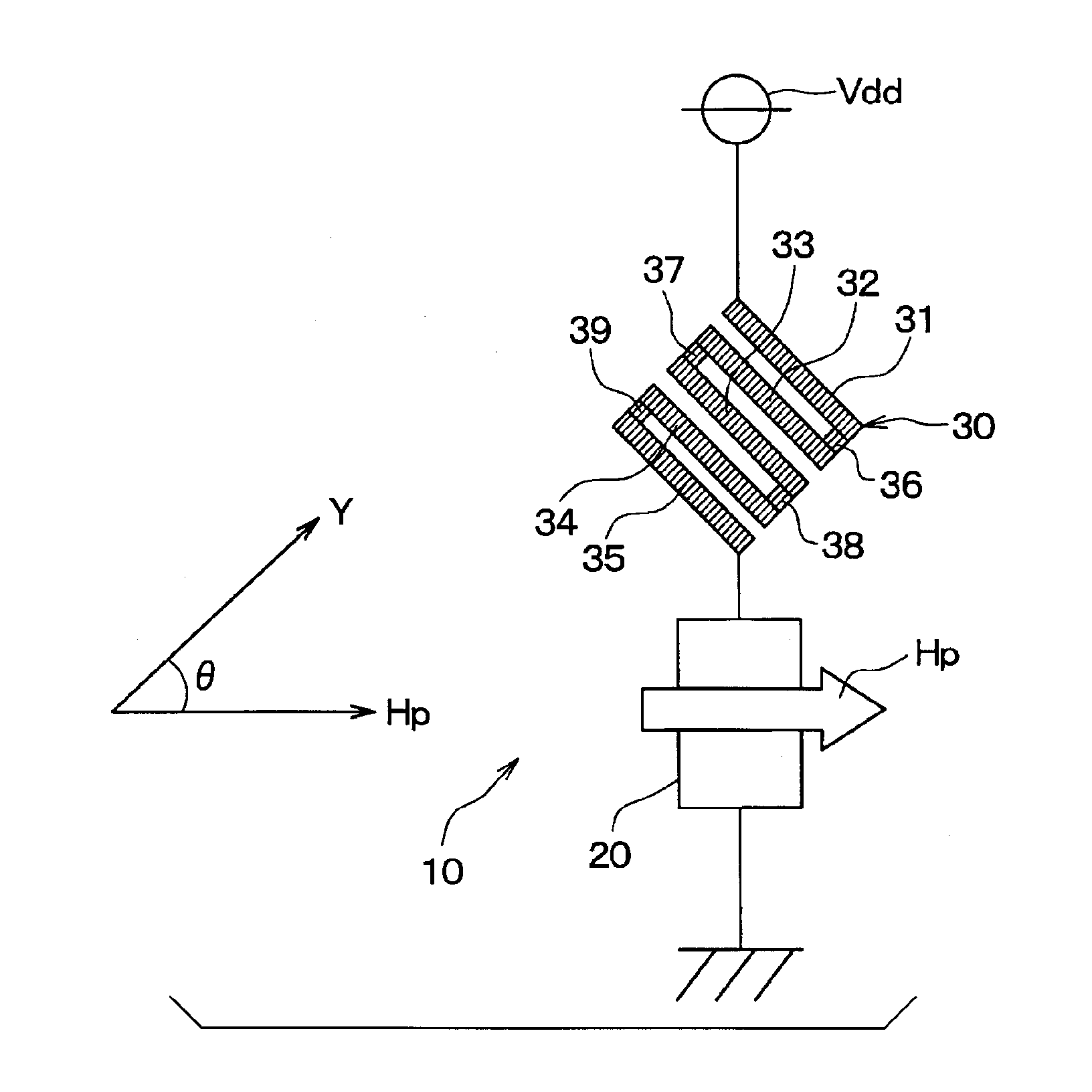
[0037]FIG. 1 shows the circuit configuration of a magnetic sensor 10 according to a first embodiment of the present disclosure. The magnetic sensor 10 includes a TMR (Tunnel Magneto-Resistance) element 20 and a corrective AMR (Anisotropic Magneto-Resistance) element 30. The TMR element 20 and the corrective AMR element 30 are series-connected between a power supply Vdd and a ground. The TMR element 20 is disposed in between the power supply Vdd and the corrective AMR element 30.

[0038]In the present embodiment, the TMR element 20 and the corrective AMR element 30 are formed in the same plane. For example, the TMR element 20 and the corrective AMR element 30 are formed to be like a membrane on an underlying insulating film formed on a substrate.

[0039]The TMR element 20 is a tunnel magnetoresistive element that includes a free layer, a pin layer, and a tunnel layer. The free layer is a ferromagnetic layer that includes a ferromagnet to detect direction Y of an external magnetic field. ...

second embodiment

[0078]The first embodiment has been described on the assumption that the magnetic sensor 10 includes one corrective AMR element 30 and one TMR element 20. A second embodiment of the present disclosure will now be described on the assumption that the magnetic sensor 10 includes two corrective AMR elements and one TMR element.

[0079]FIG. 7 shows the circuit configuration of the magnetic sensor 10 according to the second embodiment. As shown in FIG. 7, the magnetic sensor 10 according to the present embodiment includes corrective AMR elements 30a, 30b and the TMR element 20. The corrective AMR elements 30a, 30b and the TMR element 20 are series-connected between the power supply Vdd and the ground. The TMR element 20 is disposed between the corrective AMR elements 30a, 30b. The corrective AMR elements 30a, 30b are used in replacement of the corrective AMR element 30 according to the first embodiment. Characteristics of the corrective AMR elements 30a, 30b are the same as those of the co...

third embodiment

[0084]The first embodiment has been described on the assumption that the TMR element 20 and the corrective AMR element 30 are formed in the same plane. A third embodiment of the present disclosure will now be described on the assumption that the TMR element 20 and the corrective AMR element 30 are formed in different planes.

[0085]As shown in FIG. 8, the third embodiment is configured so that the TMR element 20 and the corrective AMR element 30 are formed in opposing layers via an insulating layer 25. Referring to FIG. 8, the TMR element 20 is formed forward of the insulating layer 25, whereas the corrective AMR element 30 is formed rearward of the insulating layer 25.

[0086]Further, in the present embodiment, the TMR element 20 and the corrective AMR element 30 are disposed to overlap each other. Therefore, the present embodiment makes it possible to reduce the area of the magnetic sensor 10.


PUM


Abstract

A TMR element and a corrective AMR element are series-connected between a power supply and a ground. The resistance value of the corrective AMR element is set so as to offset an output error in the rotation angle of an external magnetic field, which is included in the resistance value of the TMR element. The resistance value of the corrective AMR element is smaller than that of the TMR element. An increased voltage can be applied from the power supply to the TMR element. It is possible to increase, in the resistance value of the TMR element, the amount of change that depends on the rotation angle of the external magnetic field. This makes it possible to increase, in the output of a magnetic sensor, the amount of change that depends on the rotation angle of the external magnetic field. The sensitivity of the magnetic sensor can be increased.

Description

CROSS REFERENCE TO RELATED APPLICATION[0001]The present application is based on Japanese Patent Application No. 2012-98009 filed on Apr. 23, 2012 and Japanese Patent Application No. 2013-79703 filed on Apr. 5, 2013, the disclosure of which is incorporated herein by reference.TECHNICAL FIELD[0002]The present disclosure relates to a magnetic sensor that detects an external magnetic field.BACKGROUND ART[0003]As shown in FIG. 15, a certain conventional angle sensor that uses a TMR element 1 includes a free layer 2, a pin layer 3, and a tunnel layer4. The tunnel layer 4 is inserted between the free layer 2 and the pin layer 3.[0004]In order to detect an external magnetic field, the free layer 2 includes a ferromagnet whose magnetization direction Ha rotates in accordance with an external magnetic field. The pin layer 3 includes a ferromagnet whose magnetization direction Hb is fixed in one direction. The tunnel layer 4 varies a tunnel current in accordance with a spin state prevailing be...

Claims


Application Information

Patent Timeline
Patent Type & Authority Applications(United States)
IPC IPC(8): G01R35/00G01R33/09
CPCG01R35/00G01R33/098G01R33/093G01R33/096B82Y25/00
Inventor FURUICHI, TAKAMOTOYANO, TOSHIFUMIYOKURA, HISANORI
Owner DENSO CORP
Why Eureka
Try Eureka