Touch panel, and display apparatus provided with touch panel

a technology of touch panel and display device, which is applied in the direction of instruments, computing, electric digital data processing, etc., can solve the problems of difficult forward taper, difficult to form an even conductive film thereon, and difficult to form a forward taper, so as to reliably connect the sensor electrode and the wiring line. , the effect of high reliability

Active Publication Date: 2015-02-12
SHARP KK
View PDF14 Cites 26 Cited by
  • Summary
  • Abstract
  • Description
  • Claims
  • Application Information

AI Technical Summary

Benefits of technology

[0012]According to the present invention, in the configuration of the one glass solution touch panel, it is possible to attain a con

Problems solved by technology

However, if conductive films such as sensor electrodes and wiring lines straddle a region where the light-shielding layer is formed and a region where the light-shielding layer is not formed, there were cases in which the conductive film was disconnected due to the height difference caused by the light-shielding layer.
Thus, if the light-shielding layer is thick, the amount of light exposure in the pattern edge tends to be insufficient, which can make it difficult to form a forward

Method used


Image

  • Touch panel, and display apparatus provided with touch panel
  • Touch panel, and display apparatus provided with touch panel
  • Touch panel, and display apparatus provided with touch panel

Examples


embodiment 2

[0168]The display device 100 equipped with a touch panel may include any of touch panels 2 to 5 to be described below instead of the touch panel 1.

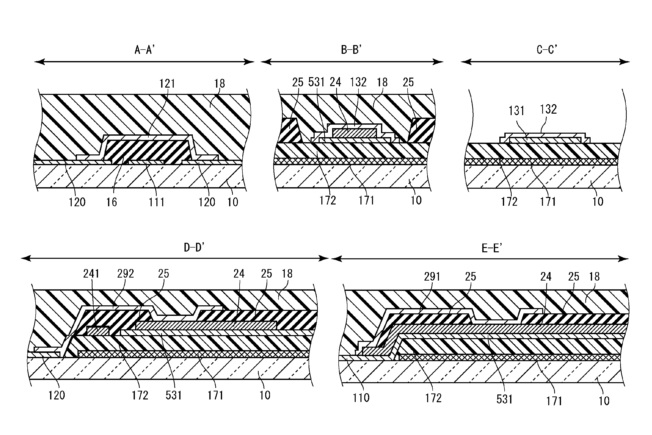
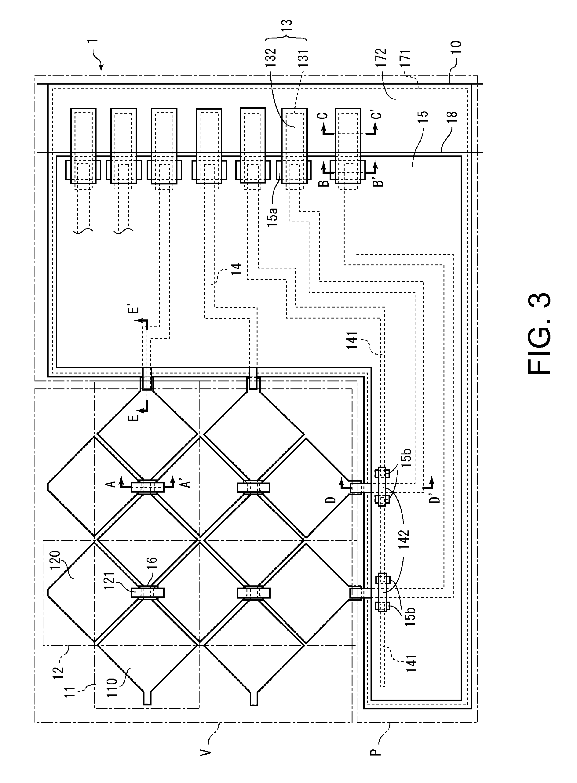
[0169]FIG. 15 is a plan view that schematically shows a configuration of a touch panel 2 according to Embodiment 2 of the present invention. FIG. 16 shows cross-sectional views of FIG. 15 along the lines A-A′, B-B′, C-C′, D-D′, and E-E′, respectively. The touch panel 2 includes a substrate 10, X electrodes 11, Y electrodes 12, terminals 13, wiring lines 24, a ground wiring line 241, insulating films 16 and 25, a light-shielding layer 171, a planarizing film 172, a protective film 18, and lead-out electrodes 291 and 292.

[0170]The touch panel 2 differs from the touch panel 1 in terms of the method by which the sensor electrodes and the wiring lines are connected.

[0171]The X electrodes 11 and the wiring lines 24 are connected through the lead-out electrodes 291. The lead-out electrodes 291 are formed over the insulating film 25 and the islan...

embodiment 3

[0188]FIG. 18 is a plan view that schematically shows a configuration of a touch panel 3 according to Embodiment 3 of the present invention. FIG. 19 shows cross-sectional views of FIG. 18 along the lines A-A′, B-B′, C-C′, D-D′, and E-E′, respectively. The touch panel 3 includes a substrate 10, X electrodes 31, Y electrodes 32, terminals 33, wiring lines 34, a ground wiring line 341, bridge wiring lines 342, insulating films 15 and 36, a light-shielding layer 171, a planarizing film 172, and a protective film 18.

[0189]That is, the touch panel 3 has a different configuration for mainly the X electrodes, the Y electrodes, and the wiring lines compared to the touch panel 1.

[0190]The X electrode 31 includes a plurality of island-shaped electrodes 310 disposed along one direction, and connecting portions 311 that connect adjacent island-shaped electrodes 310. The island-shaped electrodes 310 and the connecting portions 311 are integrally connected to each other.

[0191]The Y electrodes 32 i...

modification example of embodiment 3

[0209]FIG. 21 is a plan view that shows a schematic configuration of a touch panel 3A of a modification example of Embodiment 3 of the present invention. FIG. 22 shows cross-sectional views of FIG. 21 along the lines A-A′, B-B′, C-C′, D-D′, and E-E′, respectively. The touch panel 3 includes a substrate 10, X electrodes 31, Y electrodes 32, terminals 33, wiring lines 34, a ground wiring line 341, bridge wiring lines 342, insulating films 15A and 36, a light-shielding layer 171, a planarizing film 172, and a protective film 18.

[0210]The touch panel 3A has a different configuration for the insulating films compared to the touch panel 3. As shown in the cross-sectional views along the line D-D′ and the line E-E′, the insulating films 15A is formed so as to cover the edge of the planarizing film 172.

[0211]According to the configuration of the touch panel 3A, even if the tapering of the planarizing film 172 is not done well (if the angle is too sharp or if it is reverse-tapered), by havin...


PUM


Abstract

Provided is a highly reliable configuration of a one glass solution touch panel, in which a sensor electrode and a wiring line can be reliably connected to each other. A touch panel (1) is provided with: an insulating substrate (10) having a sensing area (V) and a non-sensing area (P); sensor electrodes (11, 12), which are formed in the sensing area (P); terminals (13), which are formed in the non-sensing area (P); wiring lines (14), which electrically connect the sensor electrodes (11, 12) and the terminals (13); a light-shielding layer (171), which is formed to cover the non-sensing area (P); and a planarizing film (172), which is formed to cover the light-shielding layer (171). The planarizing film (172) is formed only in the non-sensing area (P).

Description

TECHNICAL FIELD[0001]The present invention relates to a touch panel and a display device equipped with this touch panel, and more specifically refers to a one glass solution touch panel and a display device with this touch panel.BACKGROUND ART[0002]A touch panel is used while being bonded to a cover glass or cover film (hereinafter referred to as the “cover glass or the like”). When bonding together the touch panel and the cover glass or the like, there are cases in which air bubbles or foreign objects enter, which is a cause for decreased yield.[0003]Conventional configurations for a one glass solution touch panel are known in which the rear surface of the cover glass (surface opposite to the operating surface) or the like has formed thereon sensor electrodes, thus forming the touch panel. In other words, in this configuration, the touch panel substrate is also the cover glass (cover film).[0004]Japanese Patent Application Laid-Open Publication No. 2011-90443 discloses a projected ...

Claims


Application Information

Patent Timeline
IPC IPC(8): G02F1/1333
CPCG02F2001/133388G02F1/13338G06F3/0412G06F2203/04103G06F3/04164G06F3/0443G06F3/0446G02F1/133388
Inventor MISAKI, KATSUNORI
Owner SHARP KK
Why Eureka
Try Eureka