Energy Dissipation System For A Helmet

Inactive Publication Date: 2015-02-19
GRANT ALAN H +1
View PDF3 Cites 25 Cited by
  • Summary
  • Abstract
  • Description
  • Claims
  • Application Information

AI Technical Summary

Benefits of technology

[0007]The helmet consists of an inner and outer shell that are connected posterior of the head via a two degree freedom of movement rotating hinge. The connector allows for angular rotation about the inferior/superior and left/right axes. One potential mechanism for the connector is four springs, located left, right, inferior and superior of the connector, connected to both the inner and outer layers. The goal of the springs is two-fold—to provide resistance in the event that the outer layer rotates with respect to the inner layer about either axis in response to an impact or applied force, and to rapidly return the outer layer to its equilibrium position post-impact or after the removal of the applied force.
[0008]The inner and outer shells are formed of a hard plastic. The inner layer of the inner shell has padding on both its inner and outer surfaces. The padding on the inner surface acts to absorb energy and ensure that the helmet conforms tightly to the player's head (i.e., preventing “slip” between the helmet and the player's head). The padding on the outer surface of the inner shell is graduated in thickness from the posterior to anterior (thicker to thinner). The padding on the outer surface of the

Problems solved by technology

The result, in great frequency is: broken cranial bone

Method used


Image

  • Energy Dissipation System For A Helmet
  • Energy Dissipation System For A Helmet
  • Energy Dissipation System For A Helmet

Examples


Embodiment Construction

[0019]In describing a preferred embodiment of the invention illustrated in the drawings, specific terminology will be resorted to for the sake of clarity. However, the invention is not intended to be limited to the specific terms so selected, and it is to be understood that each specific term includes all technical equivalents which operate in a similar manner to accomplish a similar purpose.

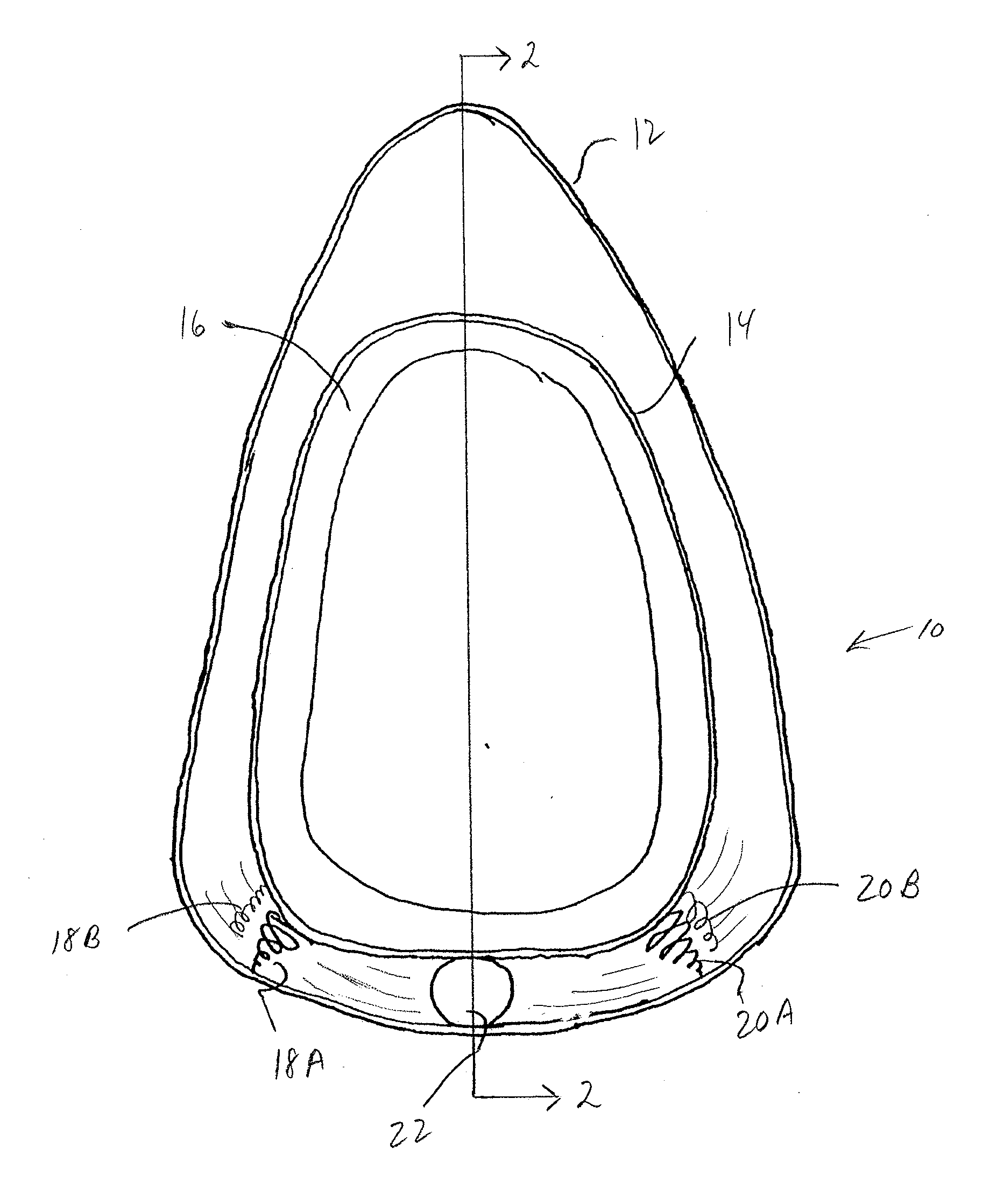
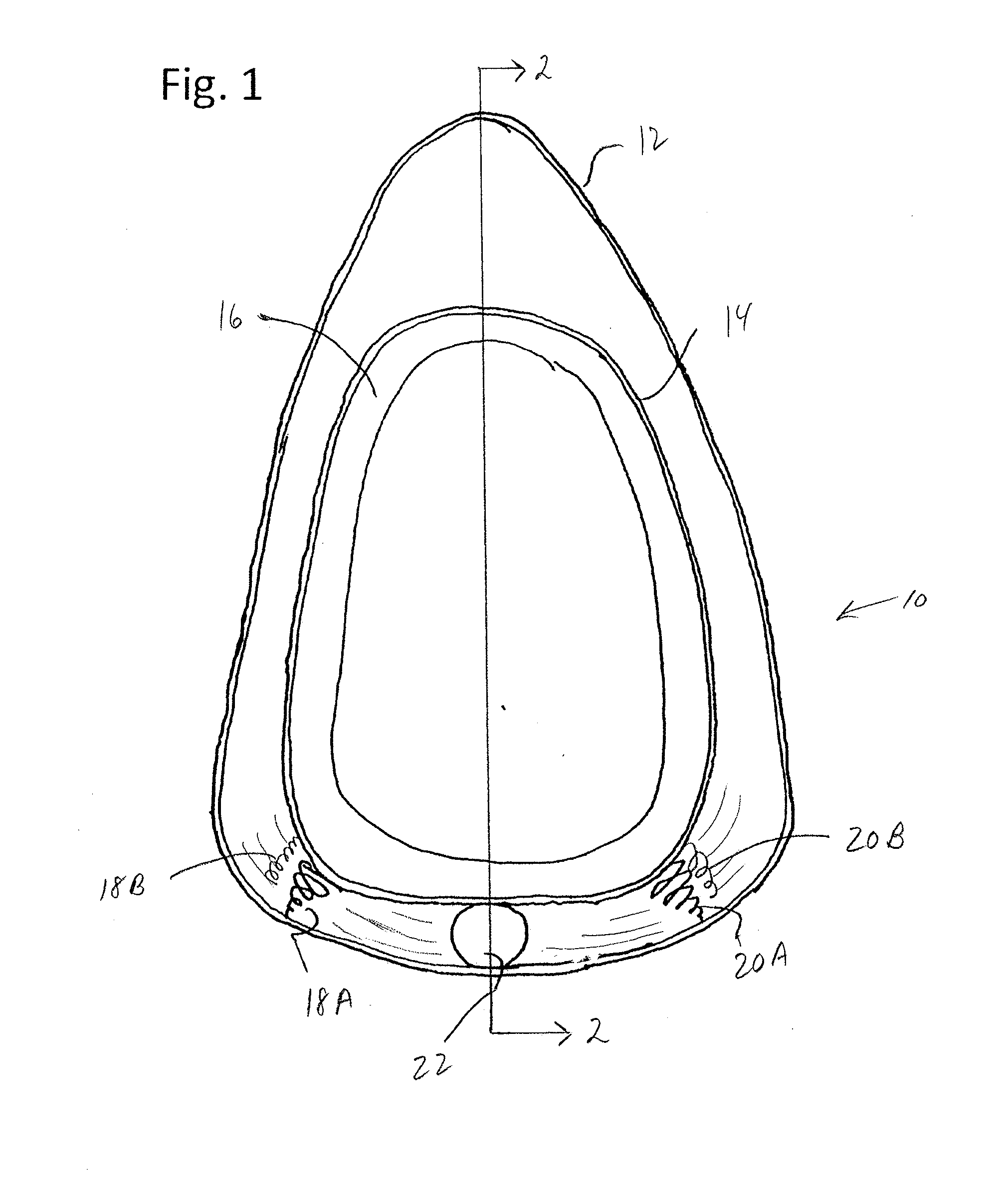
[0020]With reference to the drawings, in general, and to FIGS. 1 through 3, in particular, an energy dissipation system embodying the teachings of the subject invention is generally designated as 10. With reference to its orientation in FIG. 1, the energy dissipation system includes a rigid outer shell 12 and a rigid inner shell 14. Included within an inner layer of the inner shell is padding material 16.

[0021]A series of springs or dampers interconnect the inner shell and the outer shell. As shown in FIG. 1, springs or dampers 18A, 18B are shown on one side of a space between the inner and oute...


PUM


Abstract

A helmet consists of an inner and outer shell that are connected posterior of the head via a two degree freedom of movement rotating hinge. The connector allows for angular rotation about the inferior/superior and left/right axes. One potential mechanism for the connector is four springs, located left, right, inferior and superior of the connector, connected to both the inner and outer layers. The goal of the springs is two-fold—to provide resistance in the event that the outer layer rotates with respect to the inner layer about either axis in response to an impact or applied force, and to rapidly return the outer layer to its equilibrium position post-impact or after the removal of the applied force.

Description

FIELD OF THE INVENTION [0001]The present invention relates to the field of reducing an impact of force applied to a helmet protecting the head.BACKGROUND OF THE INVENTION[0002]From deep time, head impact collisions, have affected any and all types of human endeavor. However shock is produced from hitting an inanimate object; two or more individuals butting heads; and / or receiving contact from a moving external object. The result, in great frequency is: broken cranial bones; head / neck muscle strain; and / or brain tissue damage. Such head-impact collisions can, and do influence the post-impact future ability of the recipient to function adequately—in either a personal or societal world.[0003]Of particular note, as the importance of preventing a debilitating injury from head trauma. This may occur in sports, such as cycling, football or other contact sports.SUMMARY OF THE INVENTION[0004]The goal of the helmet of the present invention is to reduce the acceleration experienced by the head...

Claims


Application Information

Patent Timeline
IPC IPC(8): A42B3/12
CPCA42B3/125A42B3/064A42B3/06
Inventor GRANT, ALAN H.KNUTSEN, ANDREW K.
Owner GRANT ALAN H
Why Eureka
Try Eureka