
Method And Device For Condensing A Carbon Dioxide-Rich Gas Stream

a technology of carbon dioxide and gas stream, which is applied in the direction of liquid fuel engines, lighting and heating apparatus, separation processes, etc., can solve the problems of increasing water network and associated costs, pumping energy, investment cost,

Active Publication Date: 2015-02-19
LAIR LIQUIDE SA POUR LETUDE & LEXPLOITATION DES PROCEDES GEORGES CLAUDE
View PDF6 Cites 0 Cited by
  • Summary
  • Abstract
  • Description
  • Claims
  • Application Information

AI Technical Summary

Benefits of technology

The invention results in a decrease in the amount of cooling water needed and an increase in the efficiency of the compressors, which means less energy is needed overall.

Problems solved by technology

However, it will increase the water network and the costs associated therewith: pumping energy, cost of equipment such as pumps, pipes, evaporative cooling towers, fans, etc.
Indeed, the investment cost and some of the operating costs are proportional to the flow rate of the stream of water rather than (or only to a very limited extent) to the energy to be removed in the water network.

Method used


Image

  • Method And Device For Condensing A Carbon Dioxide-Rich Gas Stream
  • Method And Device For Condensing A Carbon Dioxide-Rich Gas Stream
  • Method And Device For Condensing A Carbon Dioxide-Rich Gas Stream

Examples


Embodiment Construction

[0038]The invention will be described in greater detail with reference to FIGS. 3 to 5.

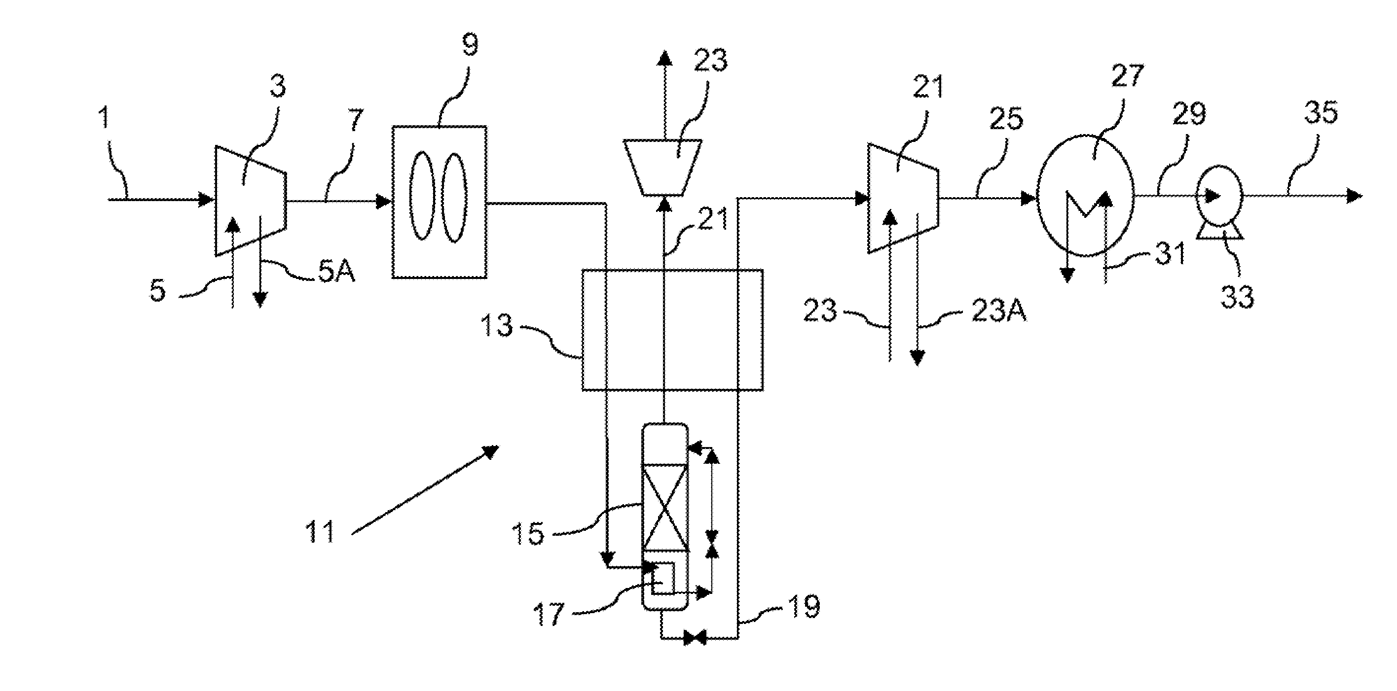
[0039]FIG. 3 differs from FIG. 1 in that the water used to cool the compressors 3 and 21 comes from the same cooling circuit as the water of the condenser 27 and has been used to condense the gas rich in carbon dioxide before being used to cool the compressors.

[0040]Thus, the water 31 is divided into two parts 31A, 31B. The part 31A is sent to the compressor 21 to cool it and the water thus heated is sent to a cooling means 53. The part 31B is sent to the compressor 3 of fluid intended for distillation and the water thus heated is also sent to the cooling means 53 which may be a cooling tower. The cooled water 51 from the cooling means 53 is once again sent to the condenser 31.

[0041]The separation means 11 may be a separation means working by cooling and condensation or by amine scrubbing or by permeation or by adsorption.

[0042]The fluid 1 is preferably a gas containing at least 50% carbon dioxide...


PUM


Abstract

The invention relates to a method for condensing a carbon dioxide-rich gas stream, wherein a stream of water heated by an exchange of heat with the carbon dioxide-rich stream, which is at least partially condensed, is sent to at least one compressor (3,21) for compressing the carbon dioxide-rich stream or a fluid, the carbon dioxide-rich stream of which is derived, in order to at least partially cool at least one stage of said compressor.

Description

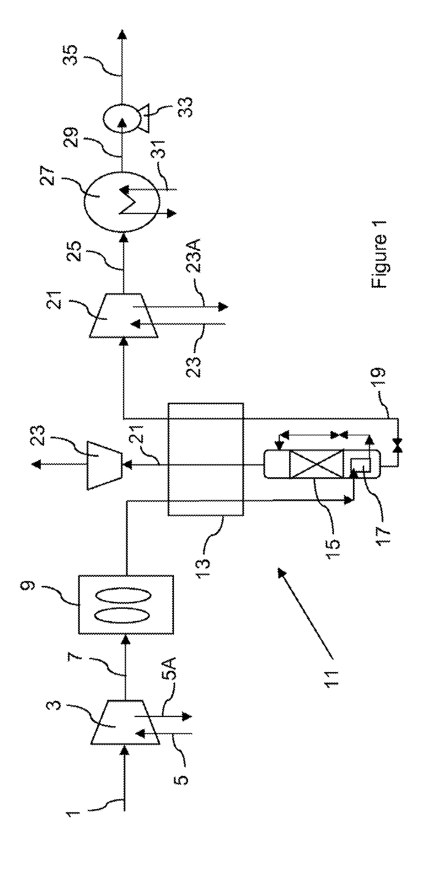
CROSS REFERENCE TO RELATED APPLICATIONS[0001]This application is a §371 of International PCT Application PCT / FR2013 / 050468, filed Mar. 5, 2013, which claims the benefit of FR1252262, filed Mar. 13, 2012, both of which are herein incorporated by reference in their entireties.TECHNICAL FIELD OF THE INVENTION[0002]The present invention relates to a method and to an installation for condensing a gaseous stream rich in carbon dioxide. A stream rich in carbon dioxide contains at least 60% carbon dioxide, or even at least 90% carbon dioxide.[0003]These percentages, like all the percentages regarding purities in this document, are molar percentages.BACKGROUND [0004]Cooling circuits using water, possibly with the addition of glycol, to cool a compressor of a stream rich in carbon dioxide are known from U.S.-A-2011 / 0265477.[0005]After a gas stream rich in carbon dioxide has been purified, it is often necessary to condense it so that it can be pumped to a pipeline.[0006]In FIG. 1, a compressor...

Claims


Application Information

Patent Timeline
IPC IPC(8): F25J1/00
CPCF25J1/0027F25J1/006F25J2230/80F25J2230/30F25J2230/04B01D53/002F28B1/02F25J3/0266F25J2200/02F25J2200/70F25J2205/04F25J2205/34F25J2210/04F25J2215/04F25J2220/82F25J2230/32F25J2240/90F25J2245/02F25J2270/12F25J2270/80F28C2001/006B01D2257/504Y02C20/40F25J2290/34F04D29/5833
Inventor DARDE, ARTHUR
Owner LAIR LIQUIDE SA POUR LETUDE & LEXPLOITATION DES PROCEDES GEORGES CLAUDE
Learn More