Holding unit for a vibration transmitter and a vibration transmission system using it

a technology of vibration transmitter and vibration transmission system, which is applied in the field of holding unit for vibration transmitter, can solve the problems of large mass, negative acoustical sound path on the feedback margin of the hearing aid system, pressure wounds or irritation of the skin, etc., and achieves the effect of reducing mechanical coupling, reducing feedback path, and improving impedance match

Active Publication Date: 2015-02-19
OTICON MEDICAL
View PDF3 Cites 38 Cited by
  • Summary
  • Abstract
  • Description
  • Claims
  • Application Information

AI Technical Summary

Benefits of technology

[0008]A transcutaneous vibration transmission system that improves the feedback margins for the hearing aid system using the vibration transmission system is disclosed. A transcutaneous vibration transmission system that may reduce the mechanical impedance mismatch during transfer of mechanical vibrations from a vibrator through the skin to the bone is disclosed.
[0027]Hereby it is possible to adjust the magnetic attraction between the (magnets of the) holding unit and the interior magnets simply by screwing / rotating the magnet(s).

Problems solved by technology

However, the constant pressurisation of the skin between the implanted parts and the vibrator may cause pressure wounds or irritation of the skin.
This acoustical sound path has negative effects on feedback margins for the hearing aid system.
This relatively large plate will have a relatively large mass that will create a mechanical impedance mismatch when transferring mechanical vibrations from the vibrator through the skin to the bone.
US 20130018218 A1 does not provide a solution to the problems caused by the transmission of the vibrations through the rather heavy magnets provided between the vibrator output and the skin surface.

Method used


Image

  • Holding unit for a vibration transmitter and a vibration transmission system using it
  • Holding unit for a vibration transmitter and a vibration transmission system using it
  • Holding unit for a vibration transmitter and a vibration transmission system using it

Examples


Embodiment Construction

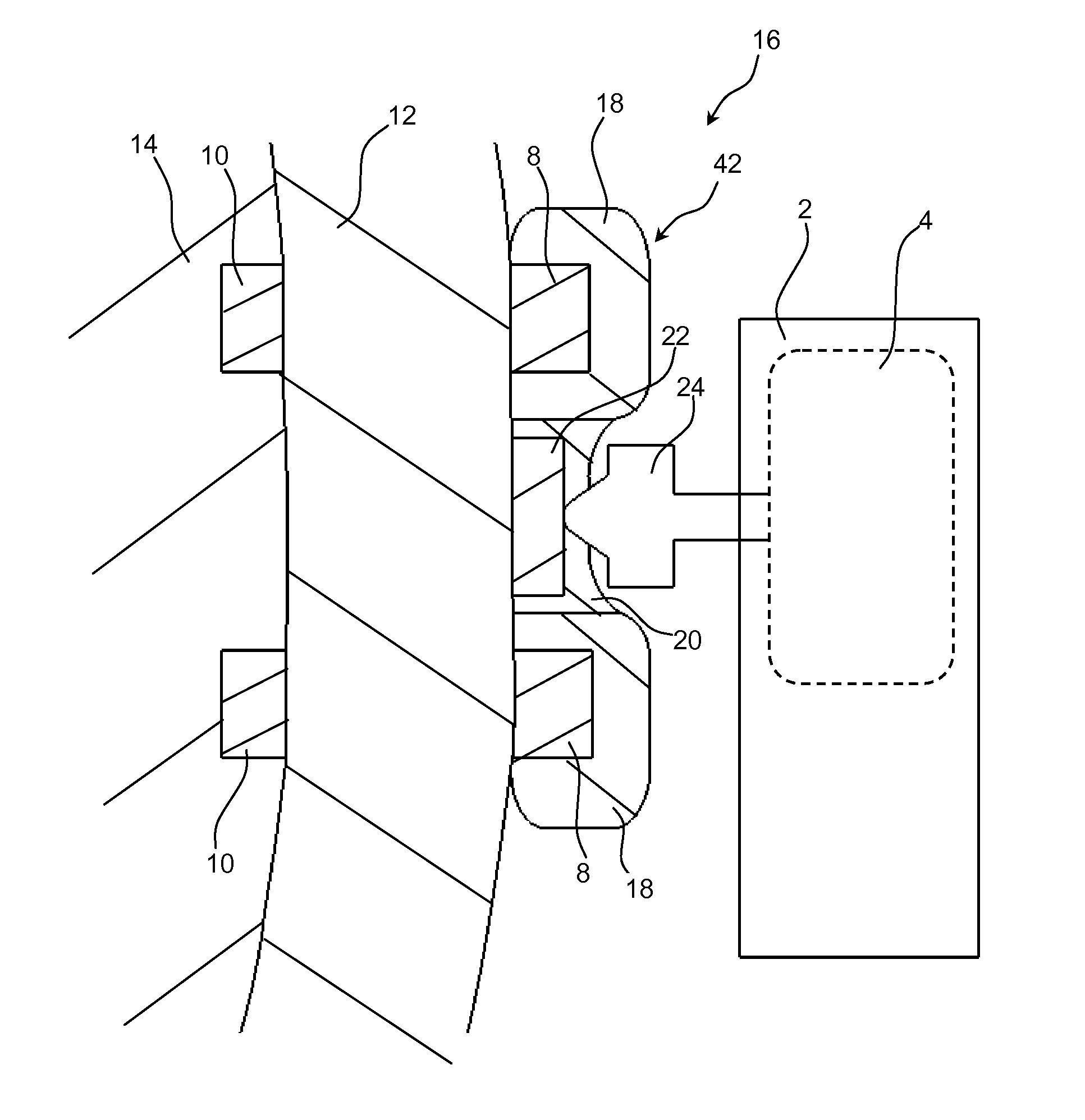
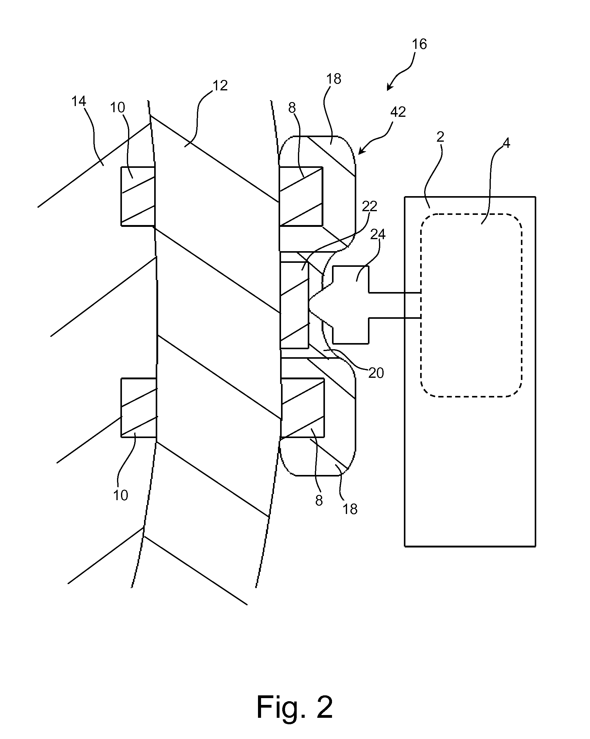
[0045]Referring now in detail to the drawings for the purpose of illustrating different aspects of the disclosure, different views of a holding unit 42 according to the invention is illustrated in FIG. 2-7 while a prior art holding unit 42 is illustrated in FIG. 1 for comparison purposes.

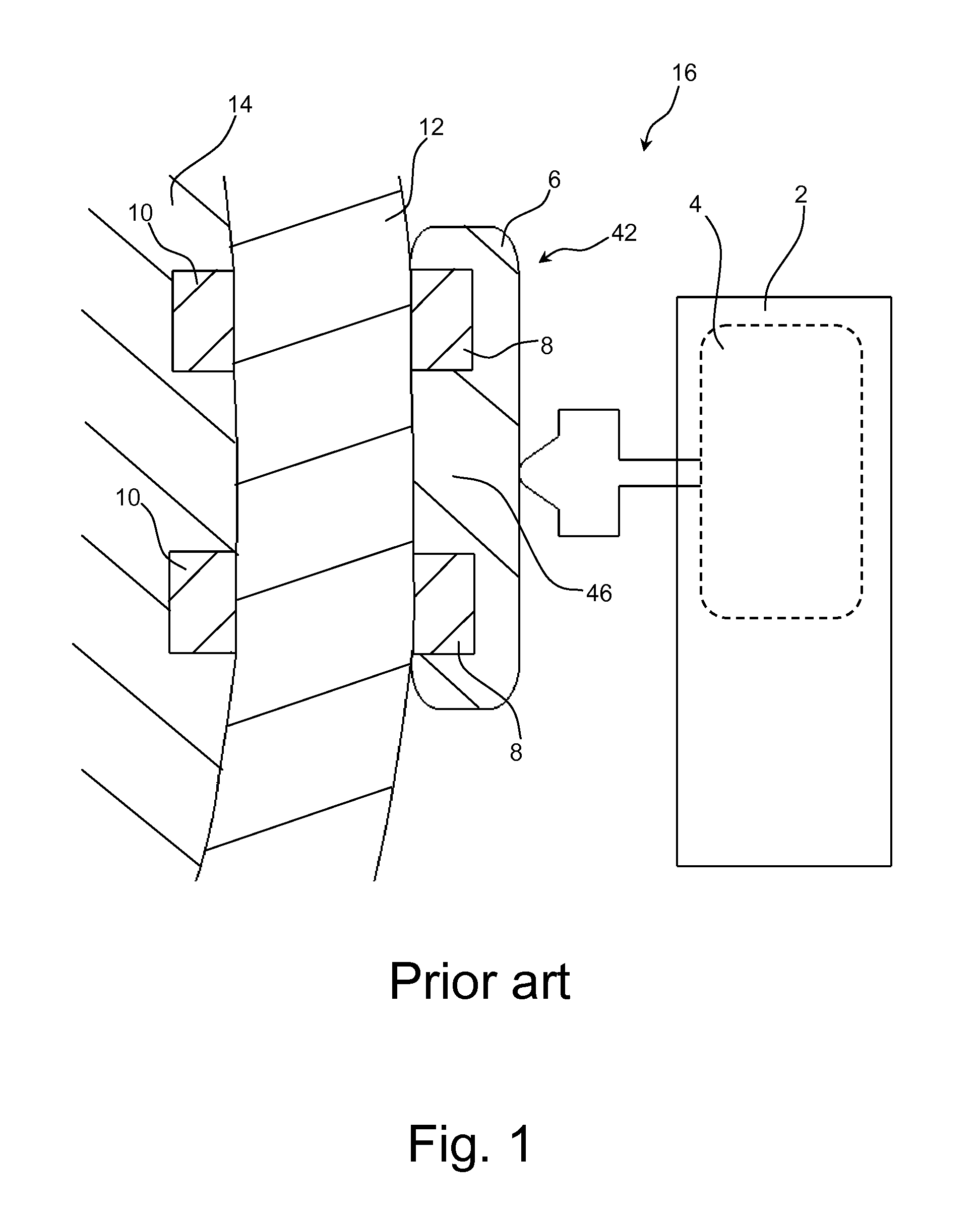
[0046]FIG. 1 illustrates a cross-sectional view of a prior art hearing aid system 16. The hearing aid system 16 consists of a holding unit 42 having a large holding plate 6 consisting of permanent magnets 8 arranged in such a way that they are configured to facing and bearing against the skin 12 of a user that has an implanted magnet 10 under the skin 12 for attachment of the holding unit 42.

[0047]The hearing aid system 16 also consists of a hearing aid device 2 consisting of a vibrator 4 that is adapted to generate and transmit vibrations via a transmission member 46 to the underlying skull bone 14 and through the bone to the cochlear. In the cochlear, the vibrations are perceived as sound by the h...


PUM


Abstract

A holding unit and a vibration transmission system are disclosed. The holding unit comprising a holding plate is configured to be attached to the skin by means of magnetic attraction between a number of external magnets that are either:a) integrated within the holding plate;b) mechanically attached to the holding plate; orc) constituting the holding plateand a number of internal magnets implanted under the skin of a hearing impaired person. The holding unit comprises a transmission member or plate member configured to transfer mechanical vibrations from a vibrator through the skin to the bone of the person. The transmission member or plate member is interconnected by a mechanical flexible coupling to the magnet(s) of the holding plate.

Description

FIELD[0001]The disclosure generally relates to a holding unit for a vibration transmitter. In order to provide hearing impaired persons a sensation of sound, a vibrator may be pressed against the skin and vibrations transmitted to the underlying skull bone and trough the bone to the cochlear. In the cochlear the vibrations are perceived as sound by the hearing impaired person.BACKGROUND[0002]It is known to maintain pressure between the skin and the vibrator output element by means of magnets / magnetisable parts implanted subcutaneously and in the vibrator output part respectively. However, the constant pressurisation of the skin between the implanted parts and the vibrator may cause pressure wounds or irritation of the skin.[0003]The prior art transcutaneous vibration transmission systems applies a relatively large plate with magnets facing the skin. This relatively large plate will act as a speaker membrane that will acoustically emit sound. This acoustical sound path has negative e...

Claims


Application Information

Patent Timeline
Patent Type & Authority Applications(United States)
IPC IPC(8): H04R25/00
CPCH04R2460/13H04R25/65H04R25/456H04R25/604H04R2225/67H04R25/606
Inventor BERN, BENGT
Owner OTICON MEDICAL
Why Eureka
Try Eureka