Spiral cam gearbox mechanism

a gearbox mechanism and spiral cam technology, applied in the direction of gears, mechanical devices, belts/chains/gearrings, etc., can solve the problems of high force transmission, high clearance between mated gear teeth, and resultant stress along the points or lines of contact in all cases, so as to reduce mechanical impedance, reduce mechanical stress, and spread the effect of stress

Active Publication Date: 2019-10-01
MOTUS LABS LLC
View PDF37 Cites 4 Cited by
  • Summary
  • Abstract
  • Description
  • Claims
  • Application Information

AI Technical Summary

Benefits of technology

[0021]In at least one version, the stationary plates provide a housing for the pivot assemblies. The torque block assemblies may pass through the main body stationary plate. The torque block(s) may also be retained and / or supported by the main body apertures. The pivot lever(s) may also be supported and / or retained by the stationary plates, and / or the void as defined by the stationary plates. The pivoting motion of the pivot lever can also coincide with a pivoting motion of the torque block that allows for the interfacing, engaging, and / or rotating of an output element.
[0023]The design of the gear block assemblies of the present invention enable a greater number of gear teeth to engage the output gear at any given time, thereby spreading the stresses associated therein across a greater area. By dramatically increasing the contact area between the gear block and the output gear at any given time the mechanical stress level is significantly decreased. In addition, the gear block assemblies of the present invention reduce backlash to zero and even preloaded conditions to create a tight connection between the power source and the powered device. This is an extremely desirable feature especially for high vibration applications. By reducing backlash to zero or preloaded condition, the mechanical impedance may also be reduced at a broad range of high vibration frequencies. Moreover, because the stresses associated with engagement of the gear block against the output gear are distributed across a greater area, the gear block mechanism may be manufactured of lighter weight, more flexible materials, which are less expensive and easier to manufacture, with no degradation in reliability. Indeed, using flexible materials further reduces the mechanical impedance at low frequencies. By reducing its weight and size, the gearbox mechanism of the present invention is adaptable to a broad range of applications that were previously impractical because of weight and space limitations.

Problems solved by technology

Because the area of contact points or lines in conventional gear trains is typically very low and the amount of power transmitted is considerable, the resultant stress along the points or lines of contact is in all cases very high.
For example, in a pair of gears backlash is the amount of clearance between mated gear teeth.
It is unavoidable for nearly all reversing mechanical couplings, although its effects can be negated.
Depending on the application it may or may not be desirable.
Consequently, zero backlash gear train devices are in many cases expensive, short lived and relatively heavy.
However, those materials are oftentimes relatively heavy, hard and difficult to manufacture.

Method used


Image

  • Spiral cam gearbox mechanism
  • Spiral cam gearbox mechanism
  • Spiral cam gearbox mechanism

Examples


Embodiment Construction

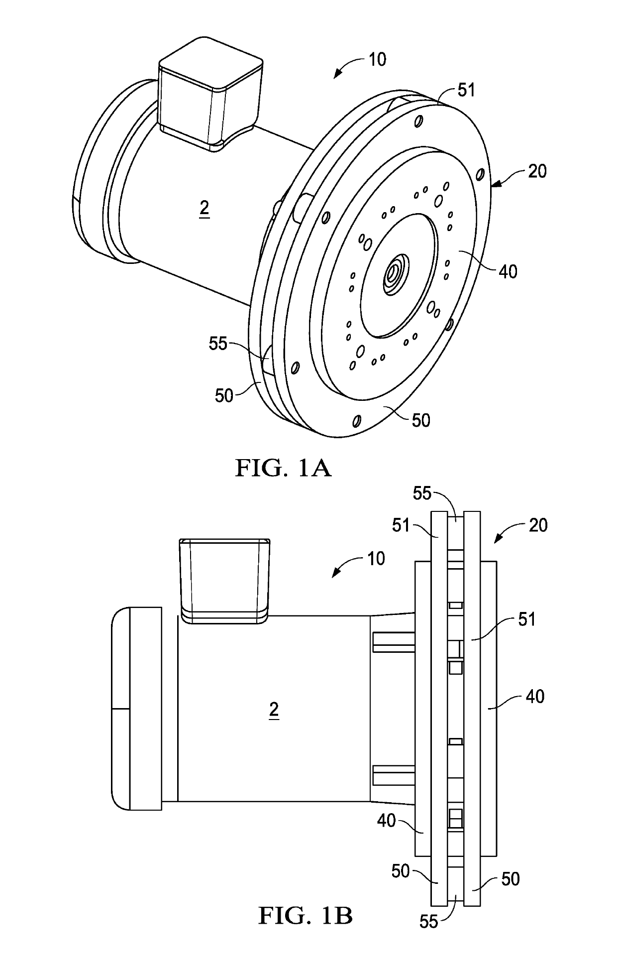
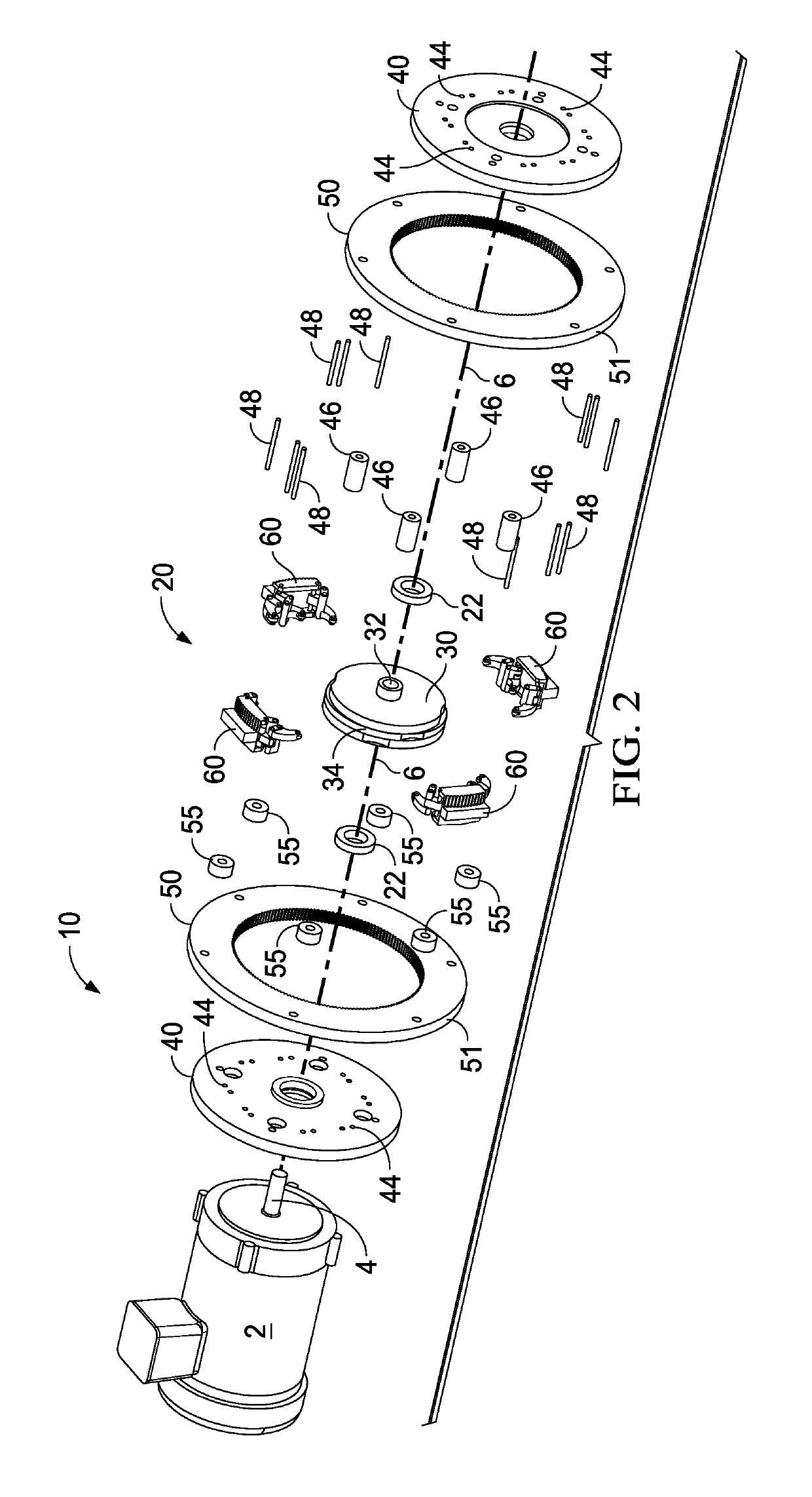
[0054]With reference to the Figures, and in particular FIGS. 1A, 1B and 2, an embodiment of a machine 10 utilizing the gearbox mechanism 20 of the present invention is depicted. The machine 10 includes a power source or actuator 2, which includes an output device 4 that transmits the power generated by the power source 2. While the embodiment shown in the Figure generally depicts the power source 2 as an electric motor and the output device 4 as an output shaft of the electric motor, it is understood that there are numerous possible embodiments. For example, output device 4 need not be directly connected to the power source 2 but may be rotatively coupled by means of gears, chains, belts or magnetic fields. Likewise, the power source 2 may comprise an electric motor, an internal combustion engine, or any conventional power source that can be adapted to generate rotative power in an output device 4. Moreover, the power source 2 may also comprise the output gear of a preceding gear tr...


PUM


Abstract

The improved gearbox mechanism of the present invention includes a plurality of cam-actuated gear block assemblies, which transfer power from a power shaft to a secondary or output gear element. Each gear block assembly includes a gear block having a surface that periodically interfaces with a secondary or output gear element. In a preferred embodiment the interface surface comprises a plurality of projections or teeth which correspond to complementary holes, projections or gear teeth on the output gear element. Each gear or torque block assembly further includes pivot assemblies, which connect or link the torque block to a cam assembly, which in turn is connected to a power source. The cam assembly comprises a set of corresponding cam elements arranged in a tandem configuration and having a unique circuitous pathway or groove formed therein so that the movement of the torque block may be controlled in three dimensions in accordance with a certain design parameter. In a preferred embodiment, a portion of the pathway is generally spiral in shape.

Description

CROSS-REFERENCE TO RELATED APPLICATION[0001]This application is a continuation-in-part application of U.S. patent application Ser. No. 14 / 995,094, filed on Jan. 13, 2016, which is a continuation application of U.S. patent application Ser. No. 13 / 795,488 filed Mar. 12, 2013 (now U.S. Pat. No. 9,261,176), the technical disclosure of which is hereby incorporated herein by reference.BACKGROUND OF THE INVENTION1. Technical Field of the Invention[0002]The present invention relates to a universal gearbox mechanism featuring cam-actuated gear block assemblies that periodically engage the output gear causing power transfer. It has particular, but not exclusive, application for use in servomotor assemblies.2. Description of the Related Art[0003]Conventional machines typically consist of a power source and a power transmission system, which provides controlled application of the power. A variety of proposals have previously been made in the art of power transmission systems. The simplest trans...

Claims


Application Information

Patent Timeline
Patent Type & Authority Patents(United States)
IPC IPC(8): F16H25/06F16H29/04
CPCF16H25/06F16H29/04Y10T74/18296
Inventor HOEFKEN, CARLOS A.
Owner MOTUS LABS LLC
Why Eureka
Try Eureka