Venting valve for a container for liquids

a technology for venting valves and containers, which is applied in the direction of functional valve types, liquid fuel feeders, machines/engines, etc., can solve the problems of dirt that is contained in fuel entering the filter body, impairing the function of the filter body, and affecting so as to achieve satisfactory air permeability and improve the service life of the venting valv

Active Publication Date: 2015-02-26
ANDREAS STIHL AG & CO KG
View PDF2 Cites 1 Cited by
  • Summary
  • Abstract
  • Description
  • Claims
  • Application Information

AI Technical Summary

Benefits of technology

[0008]The filter body is covered at the face which is facing the interior of the container by an additional filter element that substantially closes off the opening of the valve housing that opens relative to the container interior and, in this way, covers the filter body itself. Dirt particles contained in the liquid are therefore prevented from embedding in the filter body by means of the additional filter element. The service life of the venting valve is thus improved.
[0009]The material of the filter body has a first pore size and the material of the additional filter element has a second pore size. In this connection, it is provided that the second pore size of the additional filte...

Problems solved by technology

In particular when using the venting valve in a fuel tank, it has been found in practice that the dirt that is contained within the liquid container will deposit within the fil...

Method used


Image

  • Venting valve for a container for liquids
  • Venting valve for a container for liquids
  • Venting valve for a container for liquids

Examples


Embodiment Construction

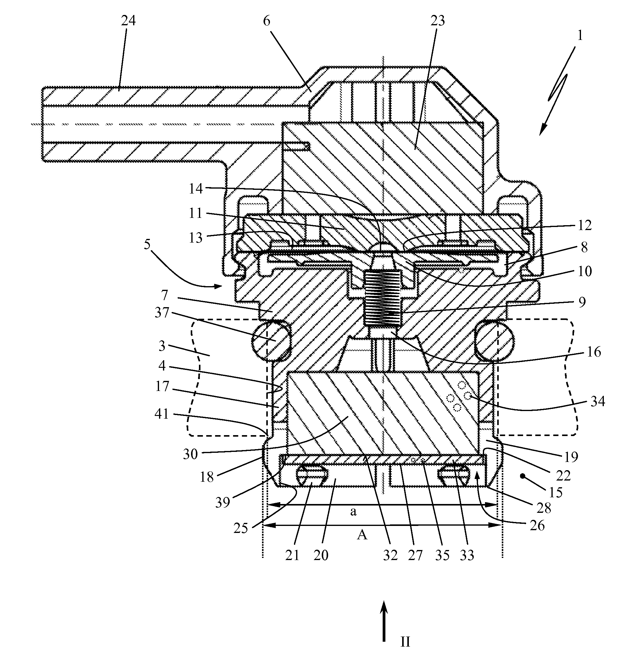
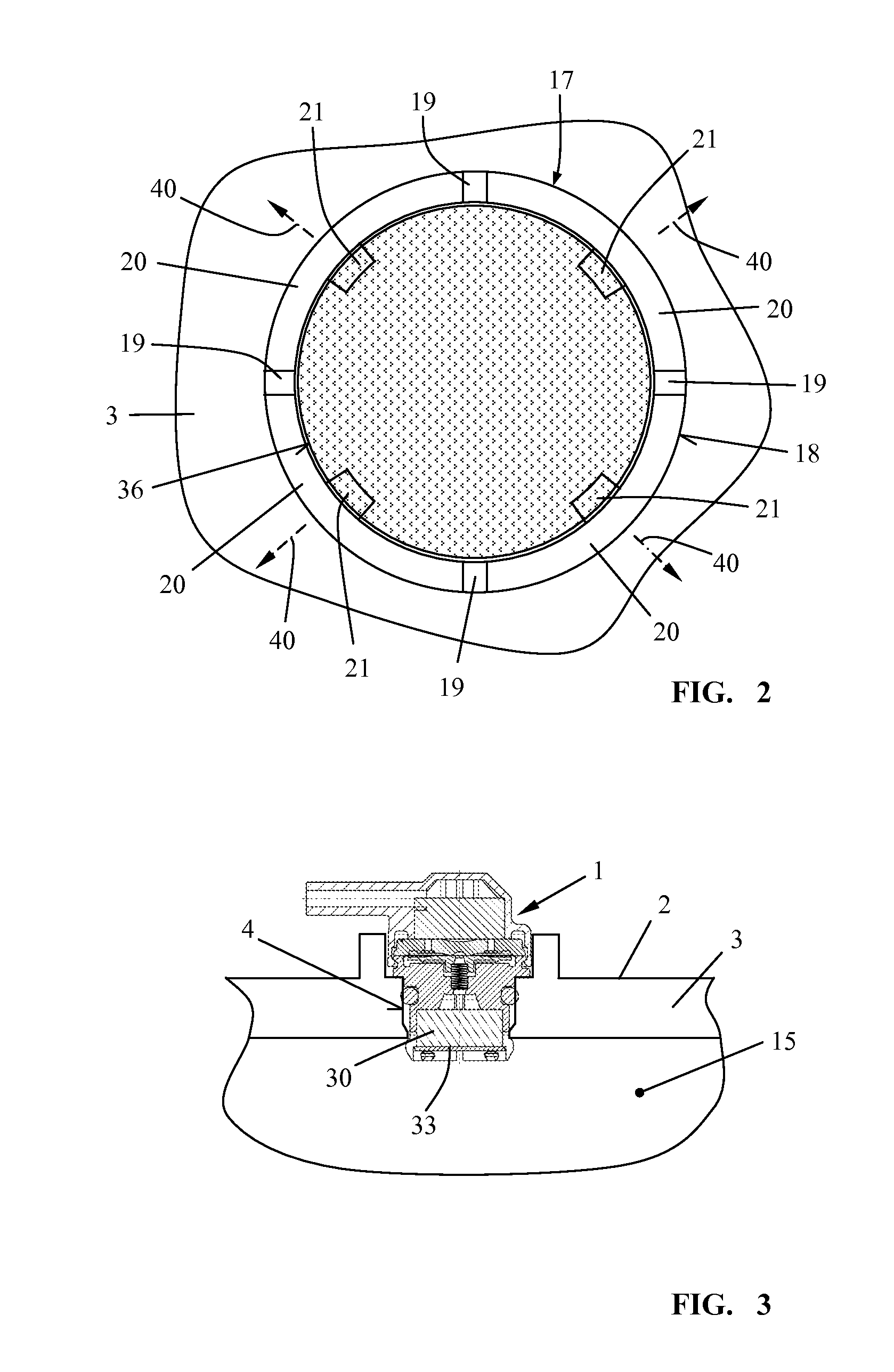
[0017]A venting valve 1 for a liquid container 2 (see FIG. 3) is illustrated in cross-section in FIG. 1. In the illustrated embodiment, the container 2 is designed as a fuel tank but can also be a container for lubricant oil, chain oil, or the like. In the container wall 3 of the liquid container 2, a mounting opening 4 for the venting valve 1 is provided.

[0018]The venting valve 1 is arranged in a valve housing 5 which is comprised of a valve cover 11 and a base member 7. Between the valve cover 11 and the base member 7, a receiving space 8 is formed in which a valve member comprising a valve plate 10 is arranged. The valve plate 10 is forced by a coil spring 9 at a predetermined force against a sealing seat 12 which is formed in the valve cover 11 closing of the receiving space 8. Between the valve plate 10 and the sealing seat 12, a sealing membrane 13 is arranged which is comprised advantageously of a plastic film and has a central membrane opening 14. The valve plate 10 together...


PUM


Abstract

A venting valve for a container for liquid has a valve housing having a pressure compensation passage connecting the container interior with the container exterior. A valve member is arranged in the valve housing and controls the pressure compensation passage. An air-permeable filter body is secured within the valve housing and covers the pressure compensation passage, wherein a face of the filter body faces the container interior. A filter element covers the face of the filter body that is facing the container interior. The filter element is a securing element for the filter body. The filter element closes off an opening of the valve housing that opens into the container interior.

Description

BACKGROUND OF THE INVENTION[0001]The invention relates to a venting valve for a container for liquids, in particular for a fuel tank in a hand-held power tool. Such a venting valve comprises a valve housing as well as a valve member which is arranged in the valve housing, wherein the valve member controls a pressure compensation passage that connects the interior of the container with the exterior of the container. An air-permeable filter body is secured within the valve housing and covers the pressure compensation passage. A face of the filter body is facing the interior of the container.[0002]A venting valve of this kind is in particular used in a fuel tank of a motor chainsaw, a cut-off machine, a trimmer, a blower, a hedge trimmer or the like. It is supposed to ensure, on the one hand, a satisfactory venting action of the fuel tank and, on the other hand, is supposed to ensure that fuel cannot escape through the venting valve, independent of the position in which the power tool ...

Claims


Application Information

Patent Timeline
IPC IPC(8): F16K24/04F02M37/00F16K17/04
CPCF16K24/04F02M37/0076F16K17/04F16K24/06F02M37/20Y10T137/7837
Inventor JOOS, STEFFEN
Owner ANDREAS STIHL AG & CO KG
Why Eureka
Try Eureka