Signal generation device and signal generation method

a signal generation device and signal technology, applied in the direction of pulse technique, process and machine control, instruments, etc., can solve the problems of inability to measure a good response, inability to monitor the response, so as to achieve automatic output of the detected value, easy and stably detect the input current valu

Inactive Publication Date: 2015-02-26
TANASHIN DENKI CO
View PDF0 Cites 1 Cited by
  • Summary
  • Abstract
  • Description
  • Claims
  • Application Information

AI Technical Summary

Benefits of technology

The present invention aims to provide a device and method for generating signals that can detect input current and phase-shifted current values simultaneously without calculating a vector of phase difference. This results in easier and more stable detection of input current and phase shifting, with automatic output of the detected values.

Problems solved by technology

Although the method of measuring a current value TO and a phase angle and calculating a leakage current using a microcomputer is chiefly used in a monitoring device or a meter, it takes time until a result is obtained due to the operations performed by the microcomputer, and continuous measurement is not allowed.
Since a time is required until an output value is stabilized, an intermittent leakage current which occurs only for a short period of time cannot be measured, and thus measurement of a good response cannot be expected.
In addition, in the vector operation processed using a microcomputer, a current value and phase differences of a voltage waveform and a current waveform which are used as a reference are measured, and a vector operation or a multiplication is performed on a result of the measurement, and in addition, since the measurement result cannot be obtained every time-delaying half-wave cycle, the burden on the microcomputer is heavy.

Method used


Image

  • Signal generation device and signal generation method
  • Signal generation device and signal generation method
  • Signal generation device and signal generation method

Examples


Embodiment Construction

[0032]The preferred embodiments of the invention will be hereafter described in detail, with reference to the accompanying drawings. In addition, the present invention is not limited to the embodiments described below.

[0033]First, a leakage current detection device according to an embodiment of the present invention will be described in detail with reference to the accompanying drawings.

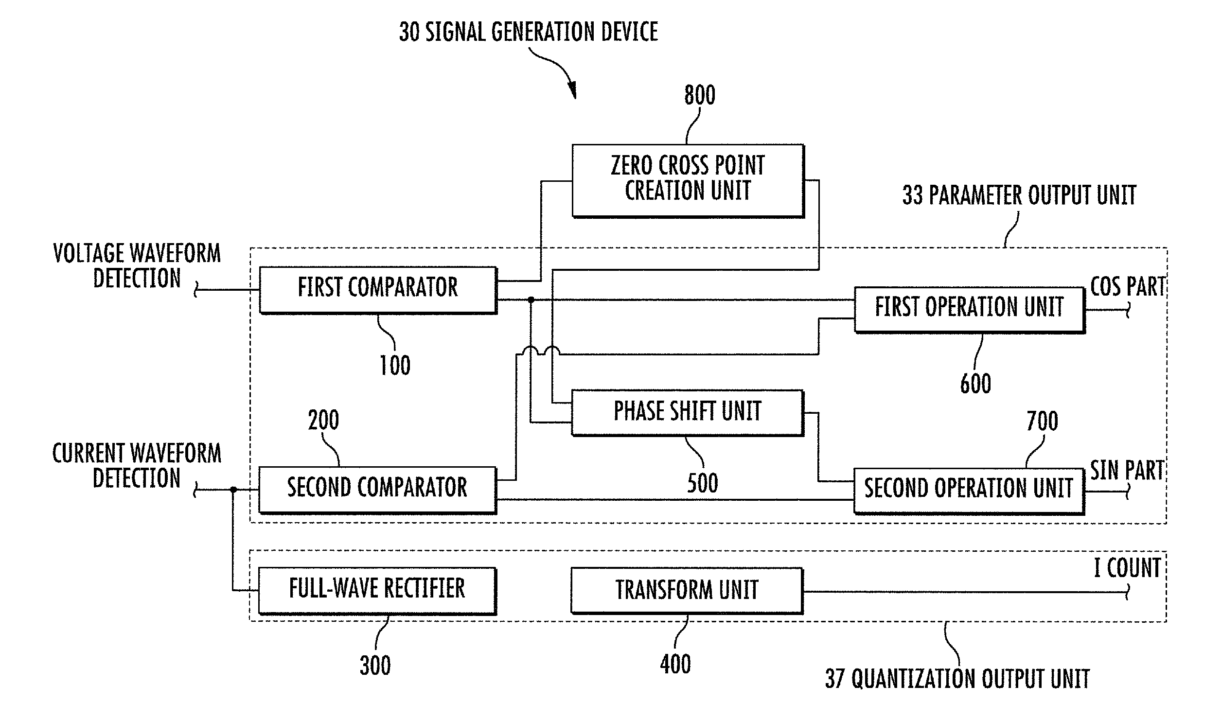
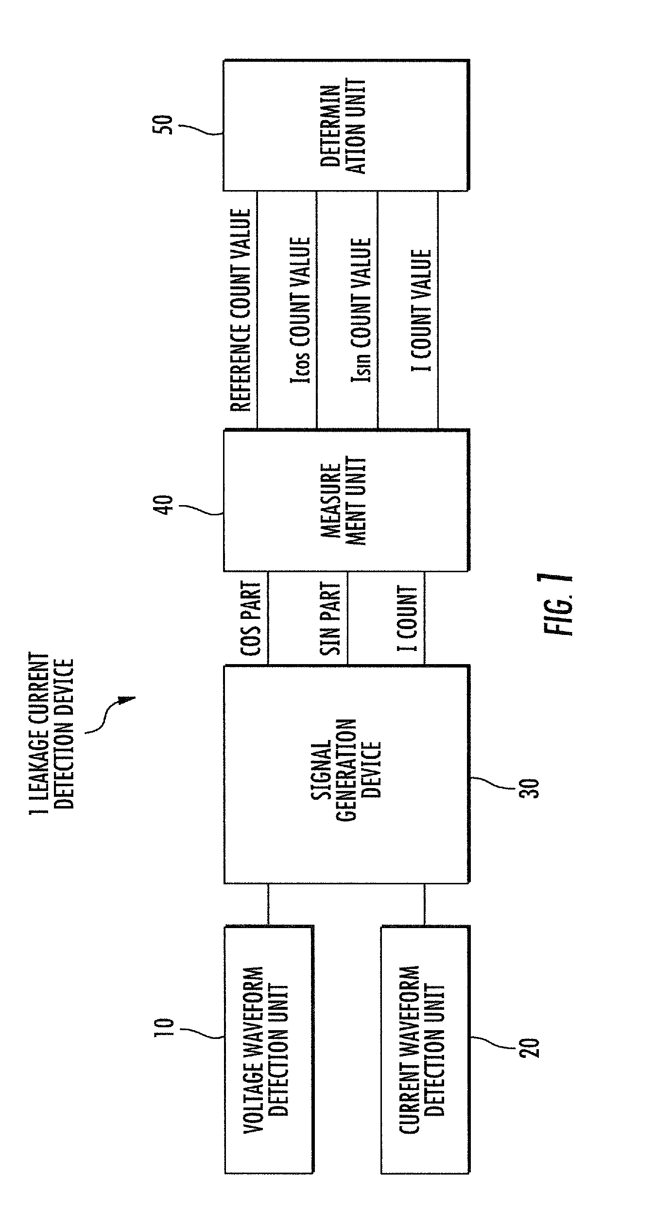
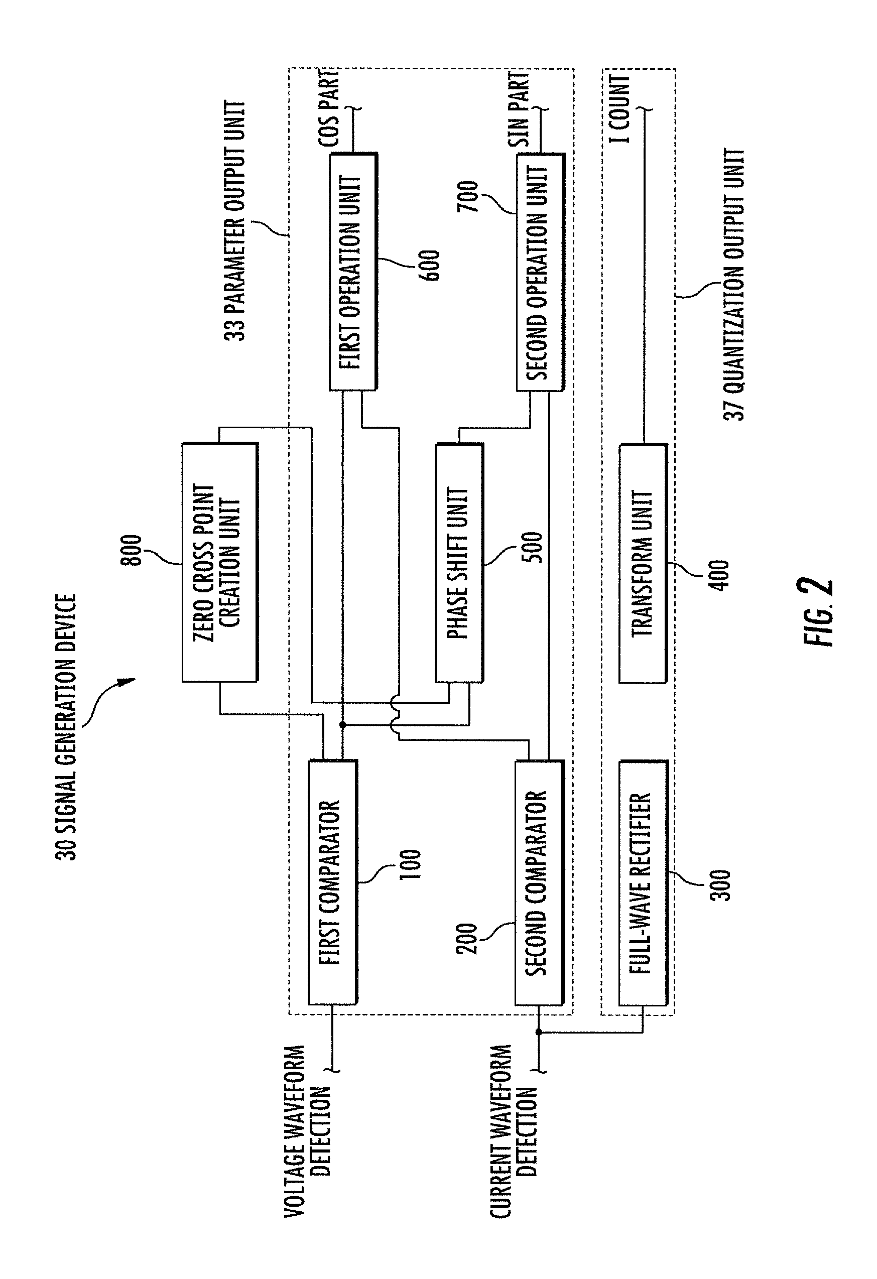
[0034]FIG. 1 is a view showing a conceptual configuration of a leakage current detection device according to an embodiment of the present invention, and FIG. 2 is a view showing a conceptual configuration of a signal generation device of a leakage current detection device according to an embodiment of the present invention.

[0035]As shown in FIG. 1, a leakage current detection device 1 according to an embodiment of the present invention includes a voltage waveform detection unit 10 for detecting a waveform of a voltage applied to a measured power line, a current waveform detection unit 20 for detectin...


PUM


Abstract

A signal generation device and a signal generation method may measure leakage currents, such as an input current value I and phase-shifted current values I cos θ and I sin θ in a short period of time and automatically output the detected values without calculating a vector of a phase difference. The signal generation device generates logical signals from a voltage waveform and a current waveform of a measured power line through first and second comparators, sets parameters, full-wave rectifies the current waveform, and performs quantization transform on the full-wave rectified current waveform using a successive ΔΣADC.

Description

RELATED APPLICATIONS[0001]This application is based upon prior filed copending Japanese application No. 2012-121421 filed May 28, 2012, the entire subject matter of which is incorporated herein by reference in its entirety.FIELD OF THE INVENTION[0002]The present invention relates to a signal generation device and a signal generation method.BACKGROUND OF THE INVENTION[0003]Recently, the request of a highly advanced information society for preventing a blackout is accomplished by a leakage current measurement method which can measure current leakage without blocking a device, in a method of measuring current leakage using an insulation resistance tester in which insulation failure management of a power line or a device accompanies a blackout.[0004]A product which measures AC current and phase difference of a device using the leakage current measurement method includes, for example, a leakage current monitoring device, a leakage current measurement device, a leakage current detection d...

Claims


Application Information

Patent Timeline
Patent Type & Authority Applications(United States)
IPC IPC(8): G01R21/127G01R21/133G01R31/02H03K17/13
CPCG01R21/127G01R31/02G01R21/133H03K17/13G01R31/2841G01R31/52G01R31/12G01R19/175
Inventor SAWADA, MASAKATSUMATSUSHITA, KENYA
Owner TANASHIN DENKI CO
Why Eureka
Try Eureka