Check patentability & draft patents in minutes with Patsnap Eureka AI!

Electromagnetic relay

a technology of electromagnetic relays and relays, applied in the field of electromagnetic relays, can solve problems such as cost increase, and achieve the effect of cost increas

Inactive Publication Date: 2015-02-26
FUJITSU COMPONENENT LTD
View PDF20 Cites 37 Cited by
  • Summary
  • Abstract
  • Description
  • Claims
  • Application Information

AI Technical Summary

Benefits of technology

The present invention provides an electromagnetic relay that can effectively extinguish arcs without increasing its cost.

Problems solved by technology

As a result, the number of processes and the number of components may be increased to thereby cause a cost increase.

Method used


Image

  • Electromagnetic relay
  • Electromagnetic relay
  • Electromagnetic relay

Examples


Embodiment Construction

[0023]In the following, embodiments of the present invention will be described with reference to the accompanying drawings.

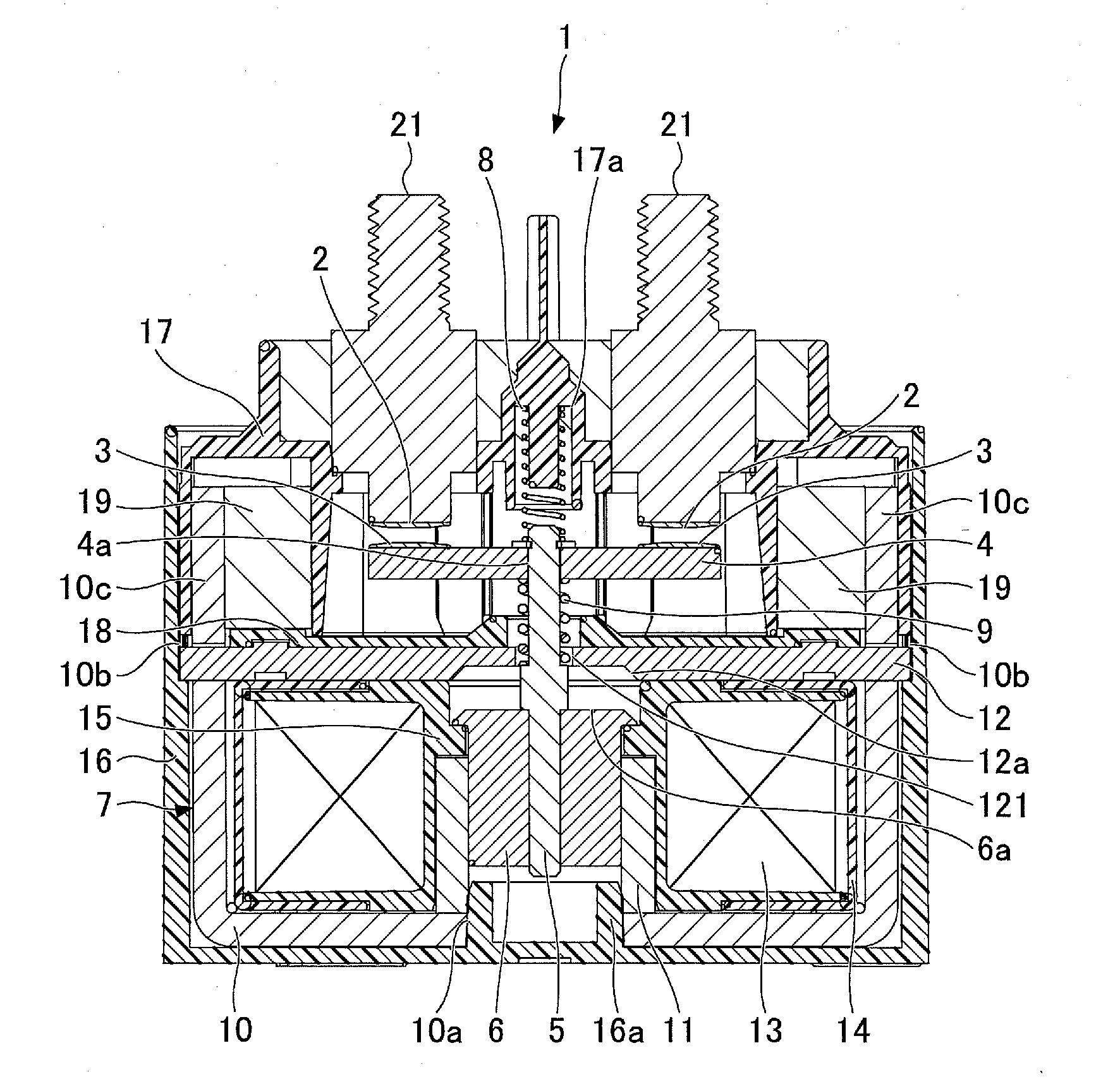
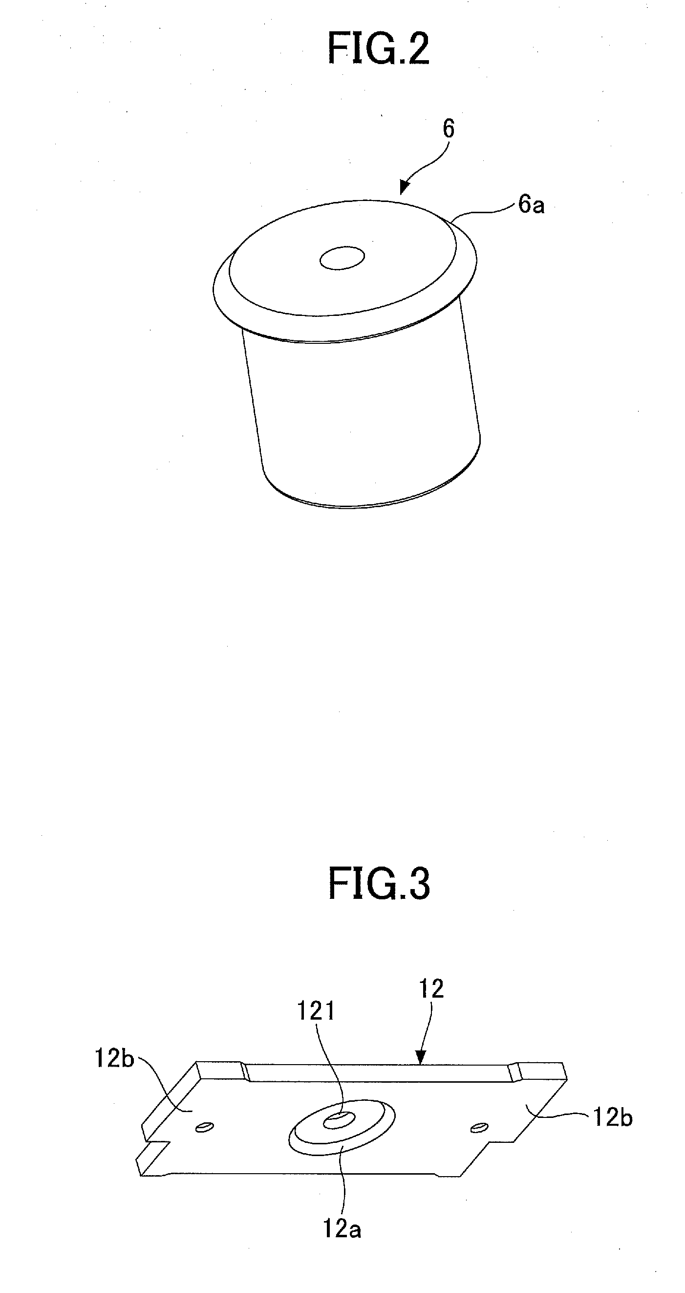
[0024]As illustrated in FIG. 1, an electromagnetic relay 1 according to an embodiment of the present invention includes a contact part including a pair of fixed contacts 2 and a pair of movable contacts 3 each corresponding to one of the fixed contacts 2. The movable contacts 3 are displaceable in directions toward and away from the fixed contacts 2. The electromagnetic relay 1 also includes a movable element 4 that holds the pair of movable contacts 3. The movable element 4 is configured to be movable in the directions toward and away from the fixed contacts 2. The electromagnetic relay 1 further includes a shaft 5 (axial core) and a plunger 6 (movable core). The shaft 5 is connected to the movable element 4. The plunger 6 is connected to the shaft 5 and is displaceable. Note that in the following descriptions, with respect to the displacement directions of the...


PUM


Abstract

An electromagnetic relay includes a contact part including a fixed contact and a movable contact, the movable contact being displaceable in an approaching / separating direction with respect to the fixed contact; a drive part including a coil, a movable core, and a fixed core, the movable core being connected to the movable contact via an axial core, and the fixed core including a first plate member having a through hole through which the axial core is inserted and a second plate member that encapsulates the coil; and a permanent magnet polarized in a direction substantially perpendicular to the approaching / separating direction. The first plate member or the second plate member includes an extension part that extends toward the contact part, the extension part being configured to hold the permanent magnet.

Description

BACKGROUND OF THE INVENTION[0001]1. Field of the Invention[0002]The present invention relates to an electromagnetic relay.[0003]2. Description of the Related Art[0004]In electromagnetic relays, passage and blockage of a current in an electric circuit is realized by opening / closing a contact part including a fixed contact and a movable contact. When the fixed contact and the movable contact are separated from each other from a contacting state, or when the fixed contact and the movable contact come closer to each other from a separated state as a result of the movable contact being moved toward / away from the fixed contact, an arc may occur when the voltage exceeds a minimum arc voltage or when the current exceeds a minimum arc current (See e.g. Japanese Patent No. 4840533).[0005]In light of the above, an arc extinction technique is used in electromagnetic relays that relies on the fact that an arc has substantially the same magnetic characteristics as a current and utilizes the magne...

Claims


Application Information

Patent Timeline
IPC IPC(8): H01H50/60H01H50/36H01H50/18
CPCH01H50/60H01H2239/044H01H50/36H01H50/18H01H9/36H01H9/443H01H50/546
Inventor KUBONO, KAZUOHASEGAWA, YOICHI
Owner FUJITSU COMPONENENT LTD
Features
  • R&D
  • Intellectual Property
  • Life Sciences
  • Materials
  • Tech Scout
  • Unparalleled Data Quality
  • Higher Quality Content
  • 60% Fewer Hallucinations
Learn More