Target detection apparatus and program

Active Publication Date: 2015-02-26
DENSO CORP
View PDF24 Cites 18 Cited by
  • Summary
  • Abstract
  • Description
  • Claims
  • Application Information

AI Technical Summary

Benefits of technology

[0011]An embodiment provides a target detection apparatus which detects a target by using

Problems solved by technology

However, it is uncertain which position on the target the radar wave is reflected from.
Hence, an error corresponding to the breadth (width) of the target (target width) is generated, which is relatively disadvantageous to measure the direction of the target.
Thereby

Method used


Image

  • Target detection apparatus and program
  • Target detection apparatus and program
  • Target detection apparatus and program

Examples


Example

[0021]With reference to the accompanying drawings, hereinafter is described an embodiment. Throughout the drawings, components identical with or similar to each other are given the same numerals for the sake of omitting unnecessary explanation.

[0022]

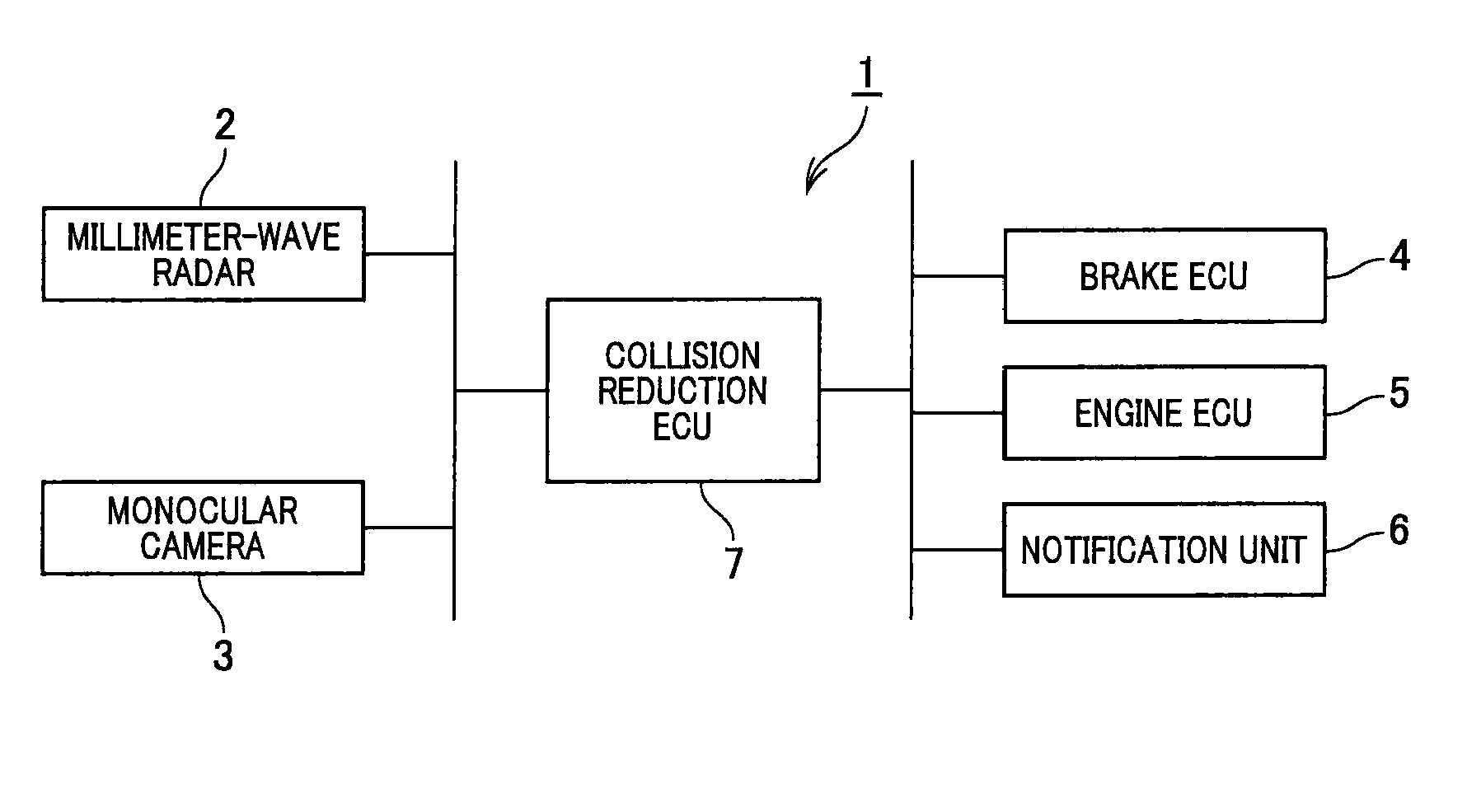
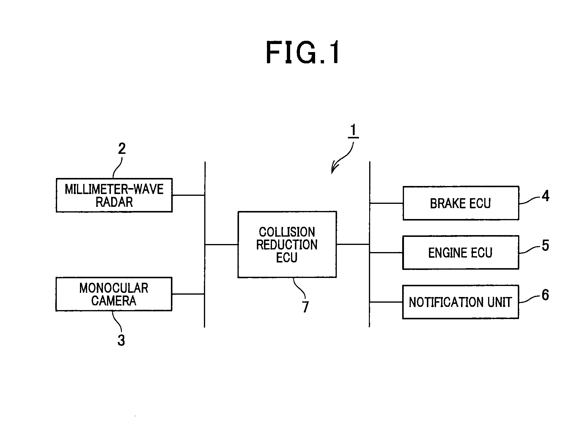
[0023]A collision reduction apparatus 1 shown in FIG. 1 is installed in a vehicle. The collision reduction apparatus 1 includes a millimeter-wave radar 2, a monocular camera 3, a brake ECU (electronic control unit) 4, an engine ECU 5, a notification unit 6, and a collision reduction ECU 7. In the collision reduction apparatus 1, the collision reduction ECU 7 is connected to the millimeter-wave radar 2, the monocular camera 3, the brake ECU 4, the engine ECU 5, and the notification unit 6 so as to communicate with each other. Note that the configuration realizing communication is not particularly limited. In addition, instead of the millimeter-wave radar 2, another in-vehicle radar may be used which uses radar waves or ultrasonic waves. I...


PUM


Abstract

A first specifying-means specifies a first-region including a first detection-point, which is of a first-target on an X-Y plane on which a width direction of a vehicle is defined as an X-axis, and a longitudinal direction of the vehicle is defined as a Y-axis. A second specifying-means specifies a second-region including a second detection-point, which is of a second-target on the X-Y plane, based on a direction of the second detection-point and a target-width, which is a width along the X-axis of the second-target. A determination means determines that the first- and second-targets are the same, provided that an overlapping portion exists therebetween. An estimation means estimates a true-value target-width, based on the direction of the second detection-point and the first detection-point, provided that the first- and second-targets are the same. A correction-means corrects a position of the second-region specified next time by using the true-value target-width as the target-width.

Description

CROSS-REFERENCE TO RELATED APPLICATION[0001]This application is based on and claims the benefit of priority from earlier Japanese Patent Application No. 2013-172283 filed Aug. 22, 2013, the description of which is incorporated herein by reference.BACKGROUND[0002]1. Technical Field[0003]The present invention relates to a technique for detecting a target by using a radar and a camera.[0004]2. Related Art[0005]For example, a collision avoidance system for a vehicle is required to accurately detect a target such as another vehicle or a pedestrian. In response to this, JP-A-2006-292475 discloses a configuration for detecting a target by using a radar and a camera. Specifically, according to the configuration disclosed in JP-A-2006-292475, a target is detected by a millimeter-wave radar and a stereo camera individually. If the position relation between the target detected by the millimeter-wave radar and the target detected by the stereo camera meets a criterion for judgment, it is determ...

Claims


Application Information

Patent Timeline
IPC IPC(8): G01S13/86G01S13/931
CPCG01S13/867G01S13/931G01S2013/9319G01S2013/93185G01S7/403G01S7/4026B60R21/013B60W30/08G01V11/00
Inventor BABA, TAKAHIRO
Owner DENSO CORP
Why Eureka
Try Eureka