
Liquid ejecting method and liquid ejecting apparatus

a liquid ejecting and liquid ejecting technology, applied in the direction of printing, other printing apparatus, etc., can solve the problems of short required time of the process of each step, long calculation time, and short process time of the device to initiate the printing action

Active Publication Date: 2015-02-26
SEIKO EPSON CORP
View PDF2 Cites 1 Cited by
  • Summary
  • Abstract
  • Description
  • Claims
  • Application Information

AI Technical Summary

Benefits of technology

The invention provides a liquid ejecting method and apparatus that reduces waiting time between when a user gives an instruction to eject liquid and when the liquid ejection is initiated. This is achieved by using a numerical value to set the amount of liquid needed, which speeds up the process of calculating the amount of liquid needed. The method also predicts the risk of the residual amount of liquid becoming too low during ejection, and takes appropriate action based on this prediction. Additionally, the method allows for quicker reinitiation of liquid ejection if it is interrupted after being initiated. Overall, the method improves the efficiency and speed of liquid ejection.

Problems solved by technology

However, in the recording device disclosed in JP-A-11-5300, since the required amount of ink is calculated on the basis of binary data of concentrated and pale after a halftone process or the sum of gradation values of individual gradation bit image data for each color after color correction processing using a color correction module, it is possible to calculate a comparatively accurate required amount of ink, but the calculation time is long.
Therefore, even in a case in which ink depletion does not occur in the middle of printing and thus, a warning is not necessary, there is a problem in that it takes time for the device to initiate a printing action after a user gives an instruction to print.
Additionally, this is not limited to ink jet printers, and the same problem also applies to liquid ejecting apparatuses that eject liquids other than ink.
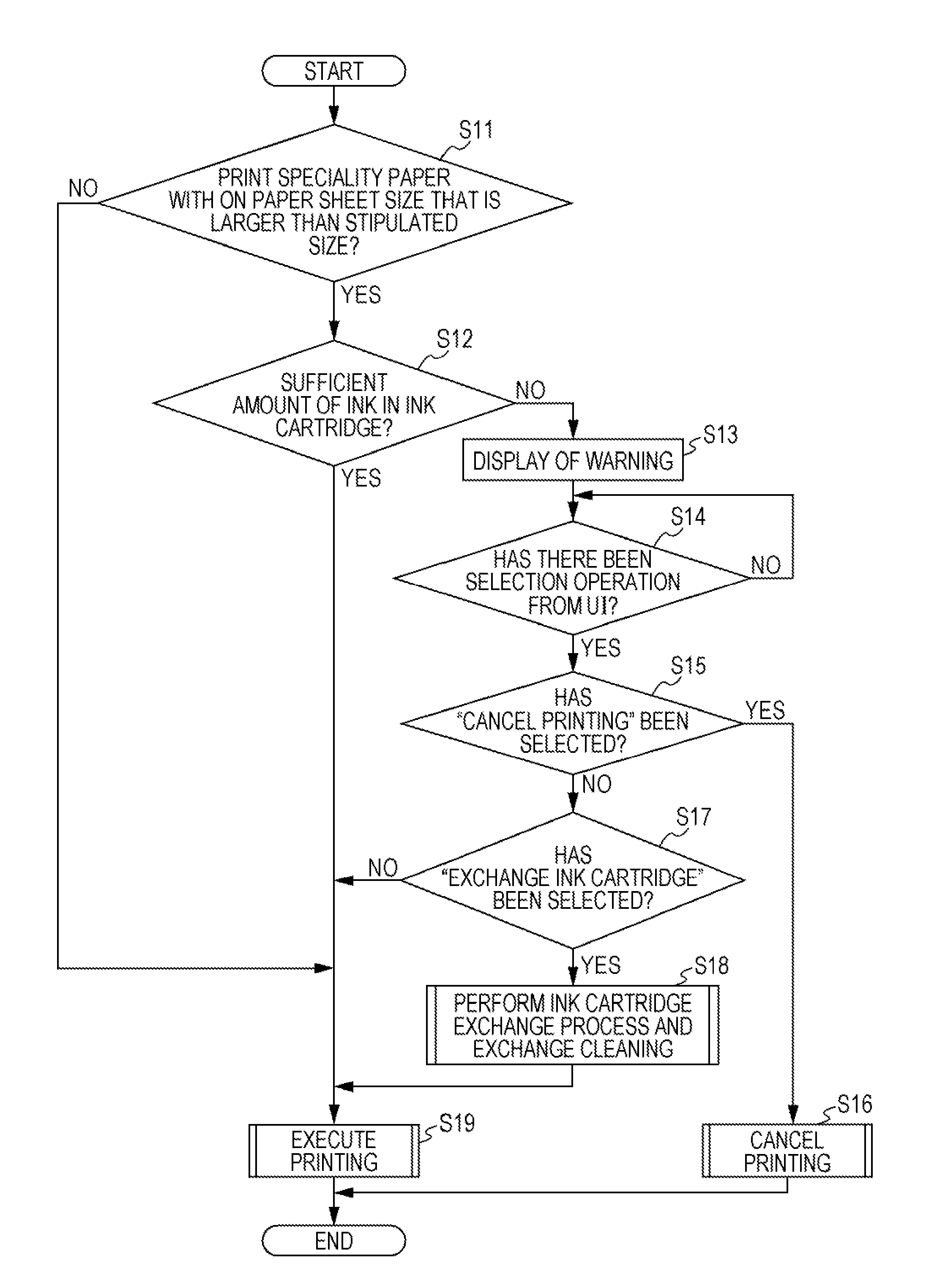
Therefore, since the required times of the processes of each step are short, a waiting time from when a user gives an instruction to eject liquid onto a target to when ejection of the liquid is initiated is comparatively short in a case in which a warning is unnecessary.
Meanwhile, in a case in which the size of the target is smaller than the stipulated size, since the risk that the residual amount of liquid becomes less than the threshold value in the middle of liquid ejection and liquid depletion is determined, is low, the processes of each step are not performed.
Meanwhile, since, in a case in which the target is a material that does not belong to a category with high receiving performance of the liquid (for example, normal paper), it is predicted that the use amount of liquid is small, and the risk that liquid depletion will occur in the middle of liquid ejection is low, the processes of each step are not performed.
Accordingly, even in a case in which liquid ejection is interrupted, the waiting time thereafter is comparatively short.
Therefore, since a required times of the processes of each step are short, and a waiting time from when a user gives an instruction to eject liquid onto a target to when ejection of the liquid is initiated is comparatively short in a case in which a warning is unnecessary.

Method used


Image

  • Liquid ejecting method and liquid ejecting apparatus
  • Liquid ejecting method and liquid ejecting apparatus
  • Liquid ejecting method and liquid ejecting apparatus

Examples


first embodiment

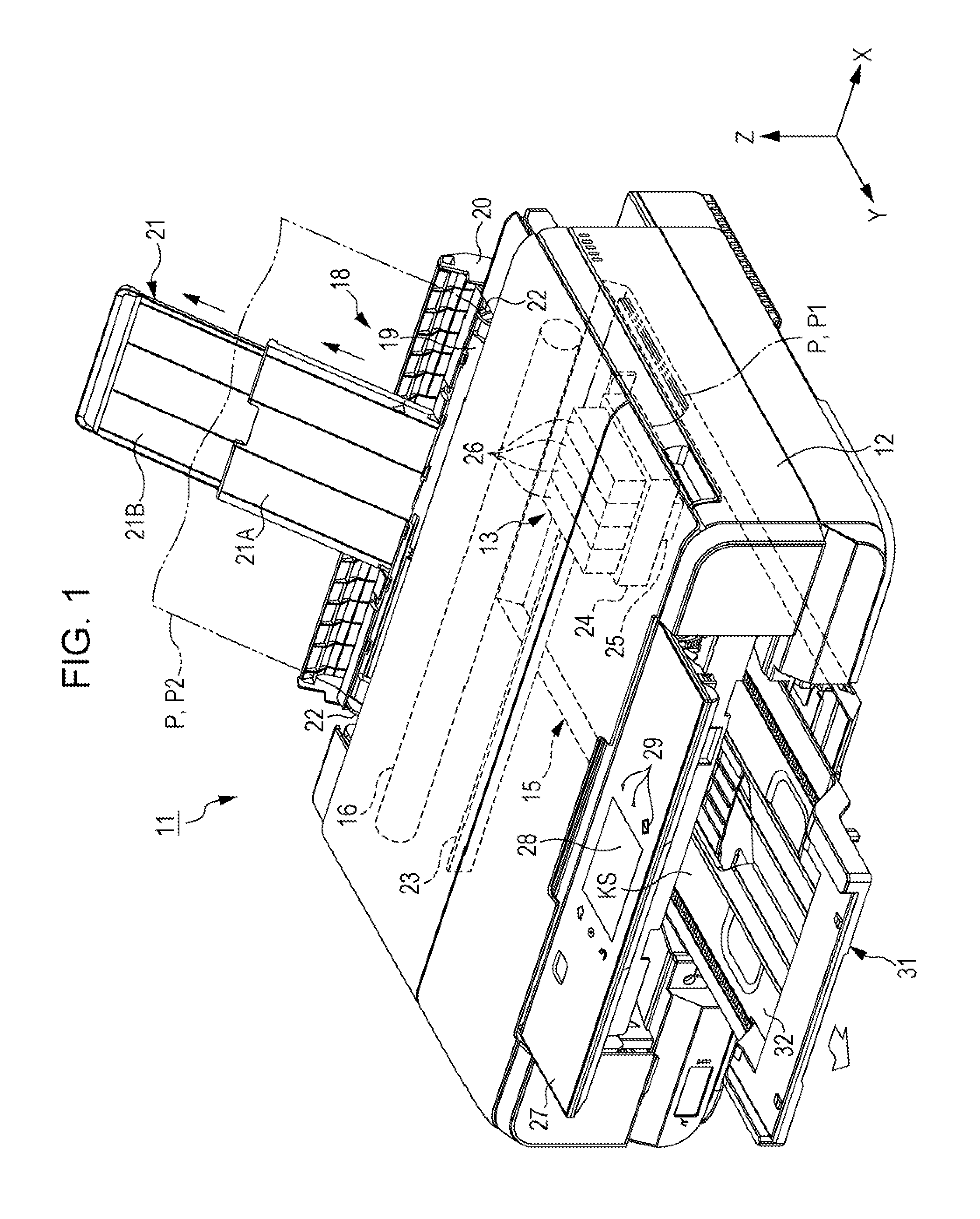
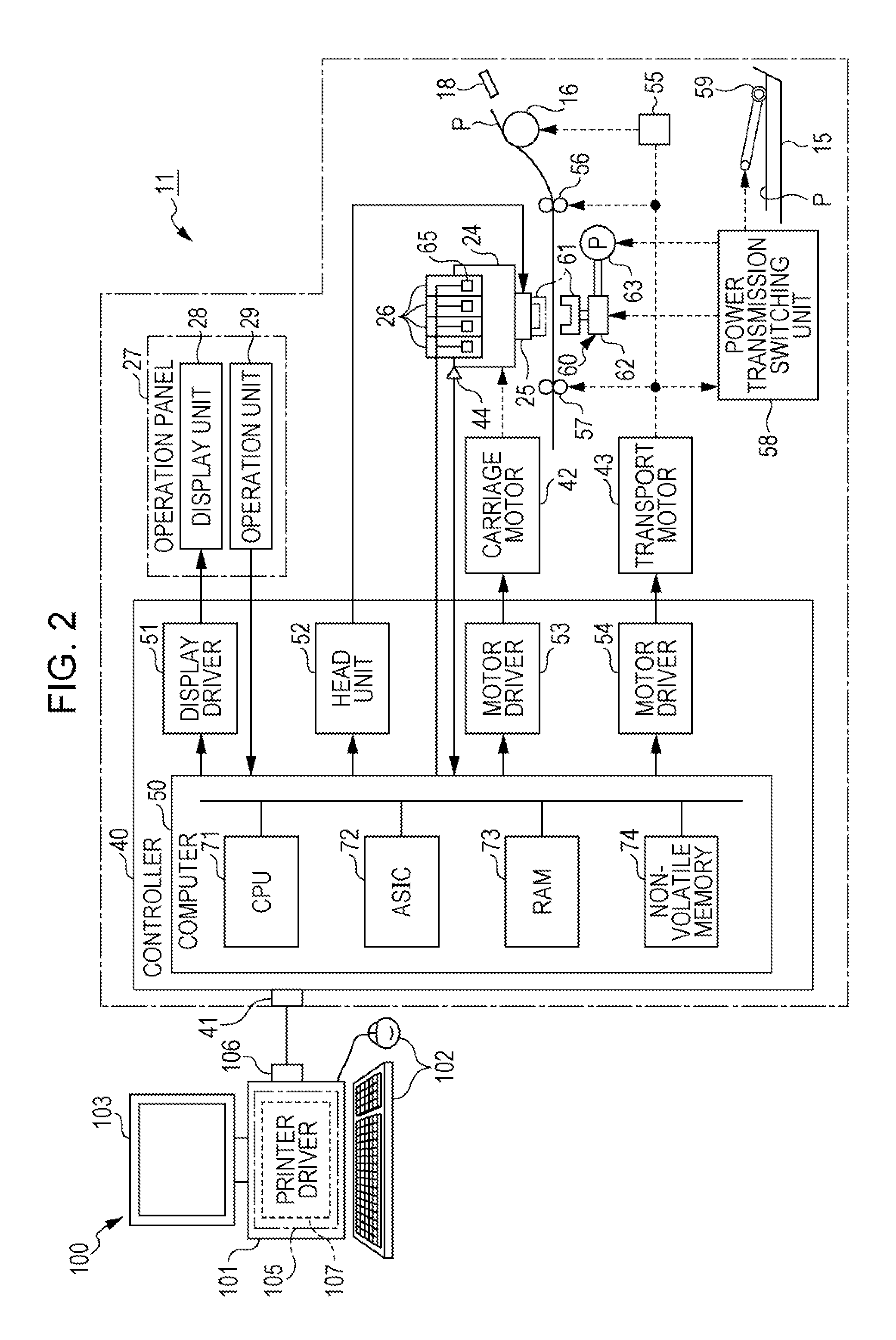
[0033]Hereinafter, an embodiment of a liquid ejecting apparatus will be described with reference to the drawings. A liquid ejecting apparatus 11 of the embodiment is a device that prints an image or the like that includes characters, graphics or the like on a paper sheet as one example of a fed target (medium) that has a sheet form by ejecting a liquid that is supplied from a liquid storage body.

[0034]As shown in FIG. 1, the liquid ejecting apparatus 11 is provided with a recording unit 13, which records an image or the like on a paper sheet P by ejecting ink as one example of a liquid, in an internal part of a device main body 12 that shows a substantially rectangular parallelepiped shape. Furthermore, a feed cassette 15 (feed tray) that is capable of storing a plurality of the paper sheets P in a laminated state is provided in the liquid ejecting apparatus 11 so as to be capable of insertion into the device main body 12. Additionally, the feed cassette 15 is not limited to the one...

second embodiment

[0108]Next, a second embodiment will be described with reference to FIGS. 2, 3, 9 etc. The present embodiment is characterized by the processes of a case in which a user selects the continuation of printing when a warning is displayed.

[0109]When an instruction that the continuation of printing selected on the warning screen G of FIG. 6 is received, the printing image data and the printing conditions data is retained in the predetermined storage region (for example, the data buffer 81) of the RAM 73 until at least the received printing is completed. Incidentally, at a time of the generation of a paper jamming error, printing has not been finished, and therefore printing image data and printing conditions data are stored in the RAM 73 since it is prior to the discarding thereof. In contrast to this, at the time of the interruption of printing due to ink running out, since printing up until that point has been completed, used data is discarded. In addition, in the liquid ejecting appar...


PUM


Abstract

A liquid ejecting method of a liquid ejecting apparatus that ejects a liquid onto a target on the basis of acquired conditions, includes acquiring a residual amount of liquid that is useable, estimating a use amount of liquid that is used in ejection of liquid using a set use amount of liquid per single target quantity that is set in advance with respect to a size of a target that is included in the acquired conditions, and performing a warning that is related to the residual amount of liquid before ejecting the liquid onto the target that is used in a case in which the residual amount of liquid after liquid ejection, which is estimated on the basis of the residual amount of liquid and the use amount of liquid, is smaller than a threshold value.

Description

BACKGROUND[0001]1. Technical Field[0002]The present invention relates to a liquid ejecting method and a liquid ejecting apparatus that has a liquid ejecting unit that is capable of ejecting a liquid such as ink.[0003]2. Related Art[0004]In a liquid ejecting apparatus such as an ink jet printer for example, an image or the like is printed on a target such as a paper sheet by ejecting ink as an example of a liquid from nozzles of a liquid ejecting head (an example of a liquid ejecting unit). In addition, liquid ejecting apparatuses of this kind are provided with ink cartridges that store ink, and are configured so that printing is interrupted and ink cartridge exchange is prompted when a residual amount of ink that is inside the ink cartridges reaches ink depletion. For example, when printing is interrupted, since printing is initiated with an ink that had temporarily dried up after ink cartridge exchange and this causes defects such as streaks being formed at the boundaries thereof, ...

Claims


Application Information

Patent Timeline
IPC IPC(8): B41J2/175
CPCB41J2002/17569B41J2/17566B41J29/38
Inventor TANAKA, TAKESHI
Owner SEIKO EPSON CORP
Learn More