
System and method for generating a traveling field free line

a traveling field and line generation technology, applied in the field of magnetic field free line generation for magnetic particle imaging, can solve the problems of limiting the applicability of the technique, and the reliability of the field free line along several axes still depends on

Active Publication Date: 2022-07-12
JULIUS MAXIMILIANS UNIV WURZBURG
View PDF10 Cites 0 Cited by
  • Summary
  • Abstract
  • Description
  • Claims
  • Application Information

AI Technical Summary

Benefits of technology

This approach enhances the scalability and efficiency of magnetic imaging by improving signal-to-noise ratio and enabling large field-of-view scanning without mechanical displacement, facilitating faster acquisition times and more reliable magnetic imaging applications.

Problems solved by technology

However, the signal-to-noise ratio in the FFP approach limits the applicability of the technique.
However, reliable displacement of the field free line along several axes still relies on mechanical displacements or involves conceptual compromises regarding resolution or size of the field of view.

Method used


Image

  • System and method for generating a traveling field free line
  • System and method for generating a traveling field free line
  • System and method for generating a traveling field free line

Examples


Embodiment Construction

[0065]The features and numerous advantages of the system and method for generating a traveling field free line according to the present invention will best be understood from a detailed description of preferred embodiments with reference to the accompanying drawings, in which:

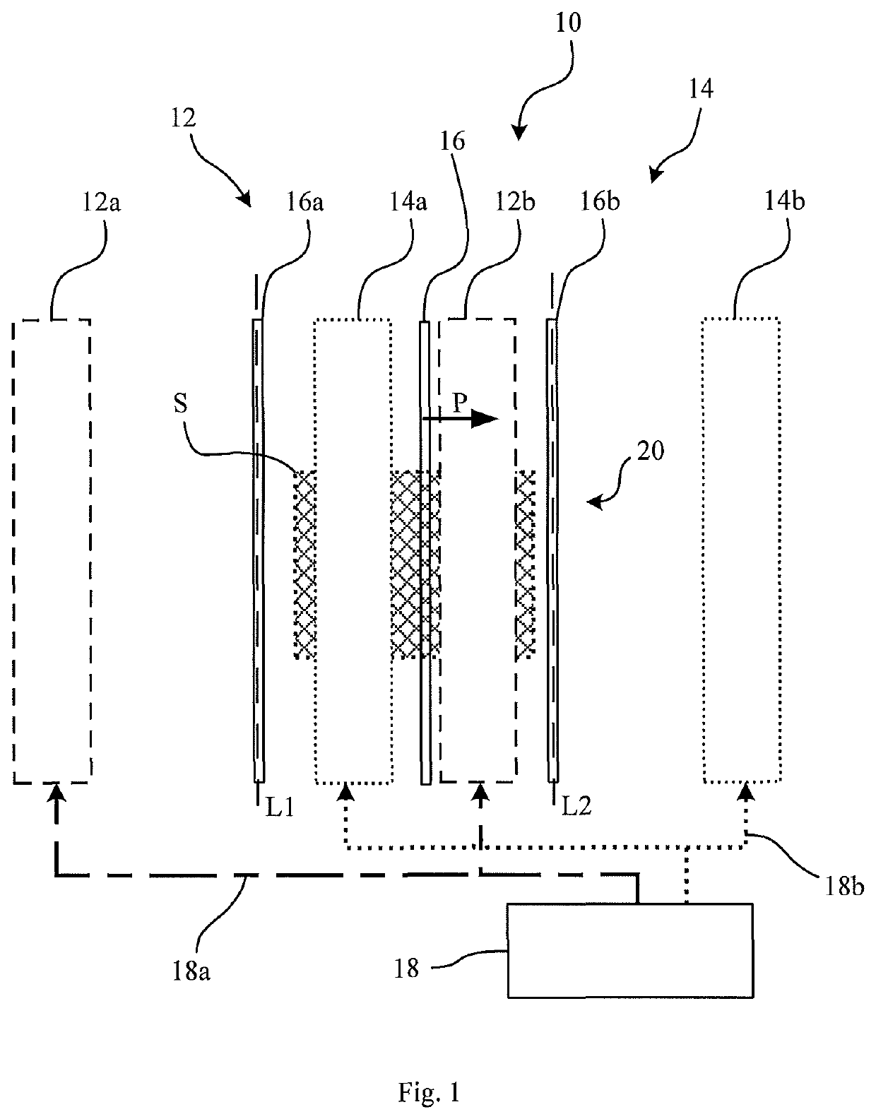
[0066]FIG. 1 is a schematic illustration of a system for generating a traveling field free line according to an example;

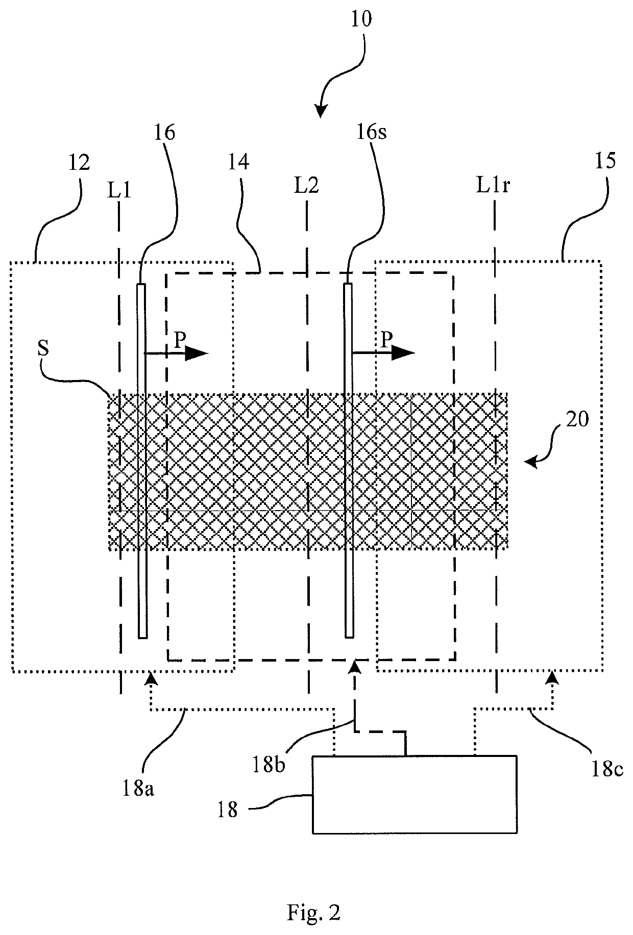
[0067]FIG. 2 is a schematic illustration of a system for generating two synchronized traveling field free lines in a probe volume according to an example;

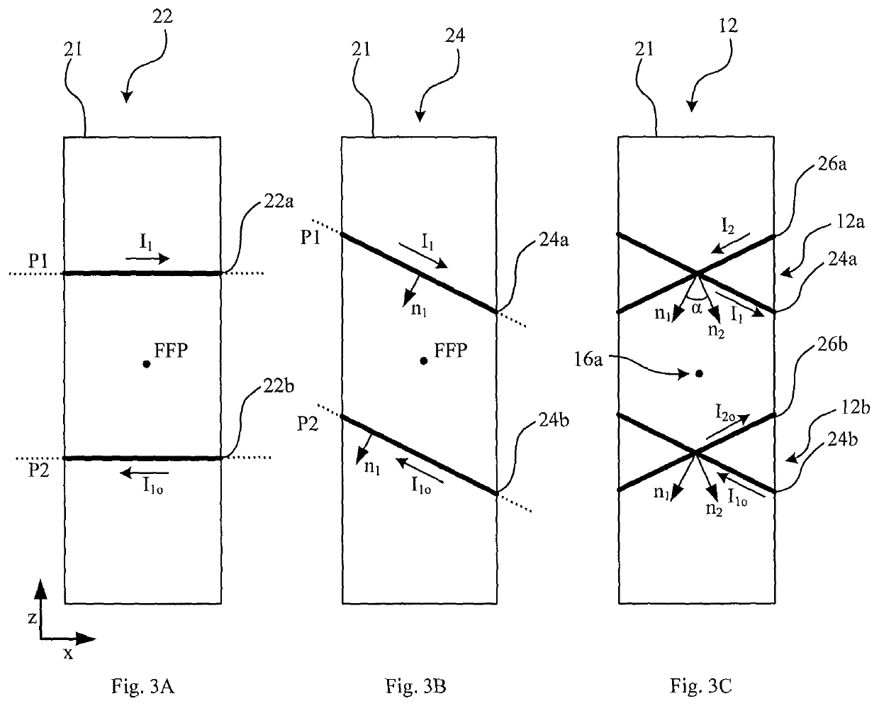
[0068]FIG. 3A is a schematic top view of a Maxwell coil assembly according to an example;

[0069]FIG. 3B is a schematic top view of a tilted Maxwell coil assembly according to an example;

[0070]FIG. 3C is a schematic top view of two combined tilted Maxwell coil assemblies in a crossed coil configuration according to an example;

[0071]FIG. 4A is a schematic illustration of the magnetic field generated by a pair of crossed coils according to an exa...


PUM


Abstract

A system for generating a traveling field free line, traveling along a propagation direction different from the orientation of said traveling field free line, said system comprising at least a first and a second coil assembly, wherein said first coil assembly is configured for generating a first stationary field free line at a first location when a current is flowing in the first coil assembly and the second coil assembly is current free, and wherein said second coil assembly is configured for generating a second stationary field free line at a second location, when a current is flowing in the second coil assembly and the first coil assembly is current free. The system further comprises a controller configured for driving the first and second coil assemblies with corresponding driving currents synchronized with each other, such that said traveling field free line travels along the propagation direction from a first location towards a second location.

Description

CROSS-REFERENCE TO RELATED APPLICATIONS[0001]This application is the national phase entry of International Patent Application No. PCT / EP2019 / 055061 filed on Feb. 28, 2019, and claims the benefit of European Patent Application No. 18165054.0 filed Mar. 29, 2018, the disclosures of which are incorporated herein by reference in their entirety.FIELD OF THE INVENTION[0002]The present invention is in the field of magnetic imaging technology. More precisely, the present invention relates to magnetic particle imaging using magnetic field free lines.BACKGROUND[0003]The treatment and diagnosis of medical conditions increasingly relies on imaging technology. Commonly used methods such as X-ray Computed Tomography (CT) and Positron Emission Tomography (PET) provide fast acquisition times with high spatial resolution but expose the patient to high-energy radiation.[0004]In contrast, magnetic imaging technology uses the characteristic response of atoms, molecules or particles in the human body to...

Claims


Application Information

Patent Timeline
Patent Type & Authority Patents(United States)
IPC IPC(8): A61B5/0515G01R33/20
CPCA61B5/0515G01R33/20G01R33/1276
Inventor VOGEL, PATRICKRÜCKERT, MARTINBEHR, VOLKER CHRISTIAN
Owner JULIUS MAXIMILIANS UNIV WURZBURG
Learn More