Driver

a technology of driving apparatus and drive shaft, which is applied in the direction of generator/motor, nanoinformatics, instruments, etc., can solve the problems of unstable stage operation, difficult control of position, and large gain of oscillation (i.e. oscillation range), and achieves small size, low power consumption, and increased recording capacity.

Inactive Publication Date: 2010-06-17
PIONEER CORP
View PDF16 Cites 6 Cited by
  • Summary
  • Abstract
  • Description
  • Claims
  • Application Information

AI Technical Summary

Benefits of technology

[0005]On the other hand, for the MEMS actuator, due to its small size, lower power consumption is desired. Moreover, in order to increase a recording capacity of the recording medium, it is aimed to increase its recording density to be extremely high and to reduce a recording pitch to be on the order of nanometers. When the data is recorded into such an ultramicro area by using the probes, performances are influenced by slight distortion in the driving position of the stage and position repeatability. Thus, it is desired to displace the stage more efficiently.

Problems solved by technology

As described above, the reason why a force is applied to the stage to oscillate the stage at a frequency lower than the minimum resonance frequency is because it is considered that if the force is applied to the stage to oscillate the stage at a frequency near a resonance frequency, the gain of the oscillation (i.e. oscillation range) becomes too large, or it becomes harder to control a position at a frequency higher than the resonance frequency, resulting in unstable operations of the stage (i.e. operations of the MEMS actuator).

Method used


Image

  • Driver
  • Driver
  • Driver

Examples


examples

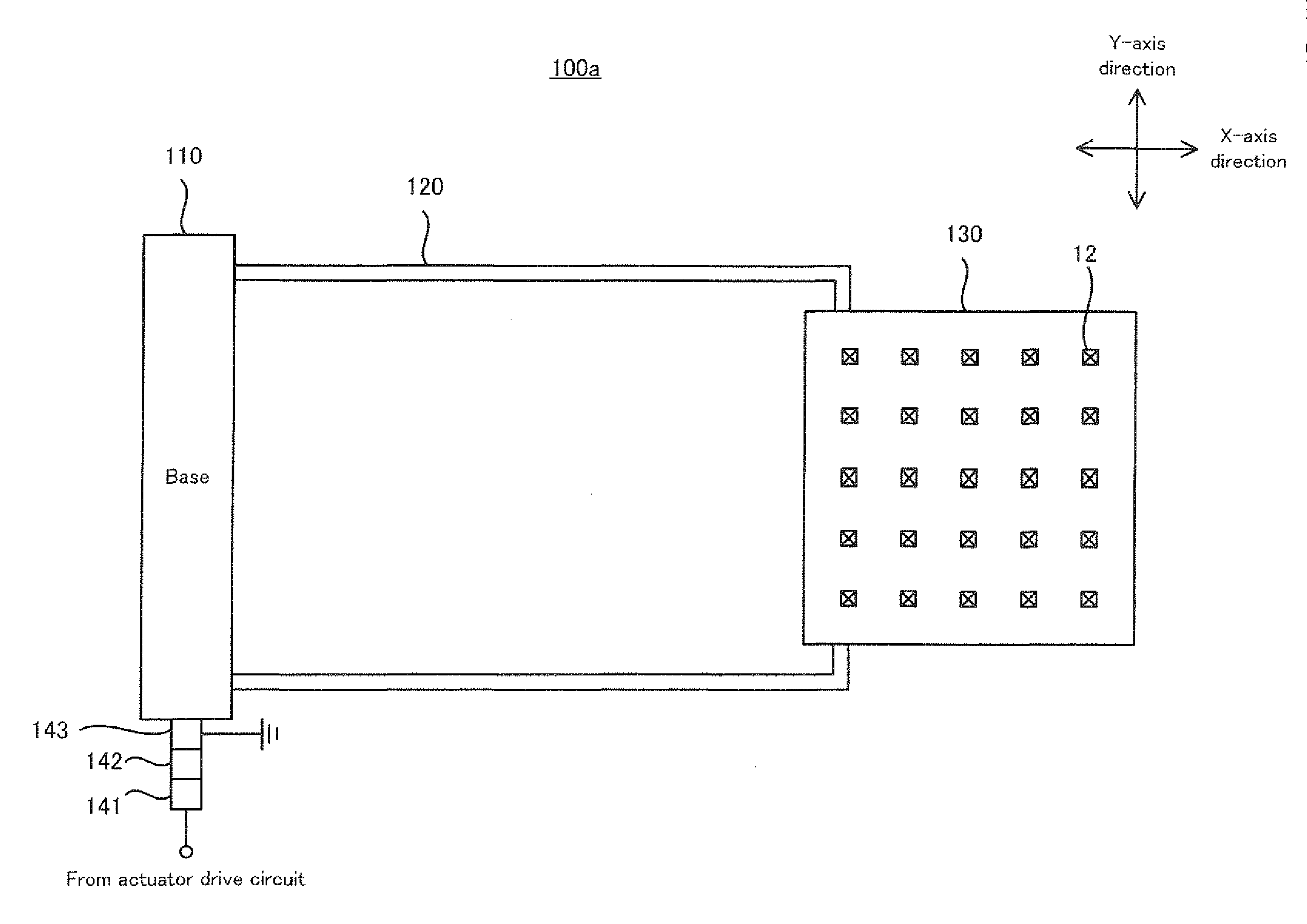
[0078]Hereinafter, examples of the driving apparatus of the present invention will be described with reference to the drawings.

[0079](1) Information Recording / Reproducing Apparatus

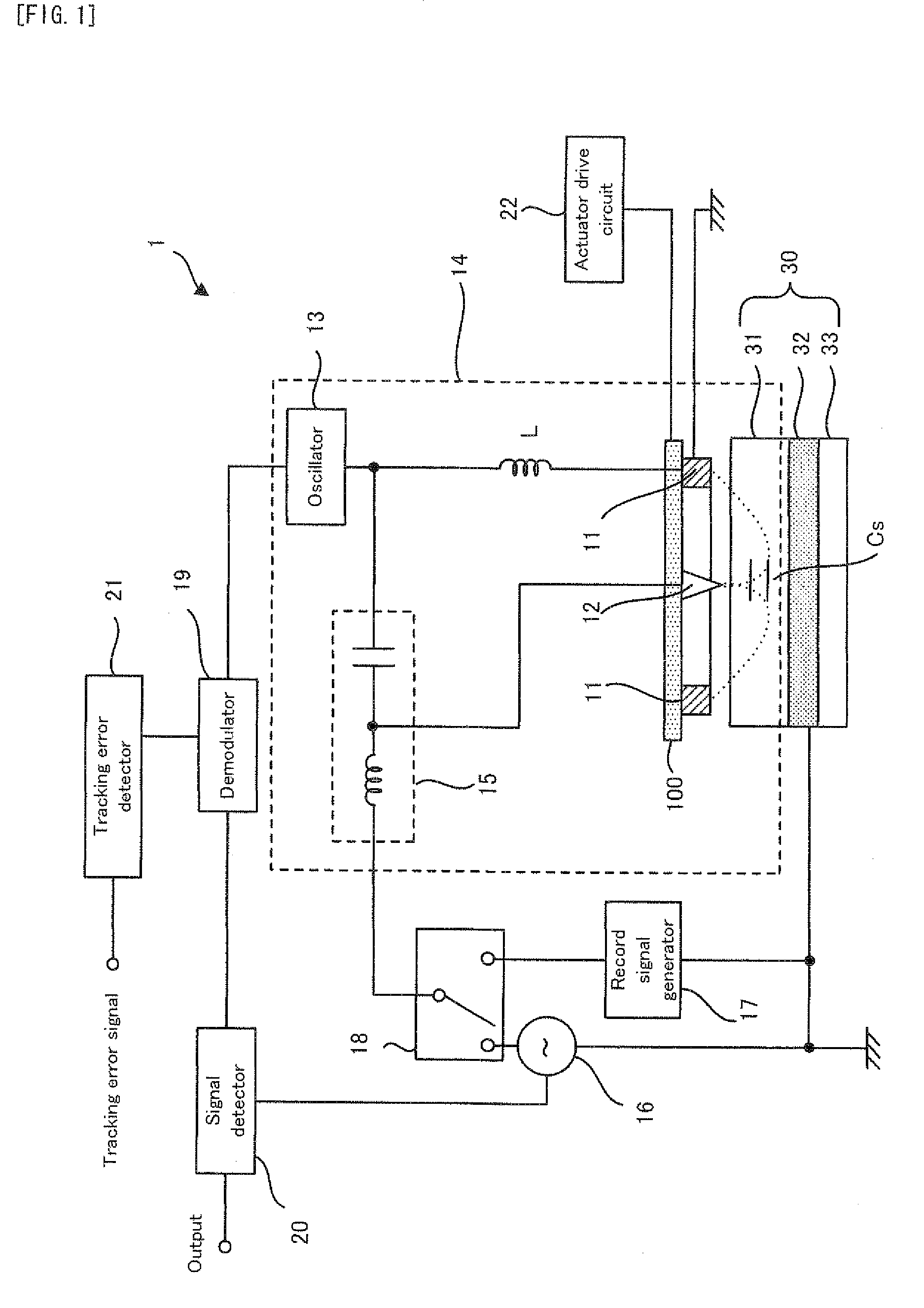
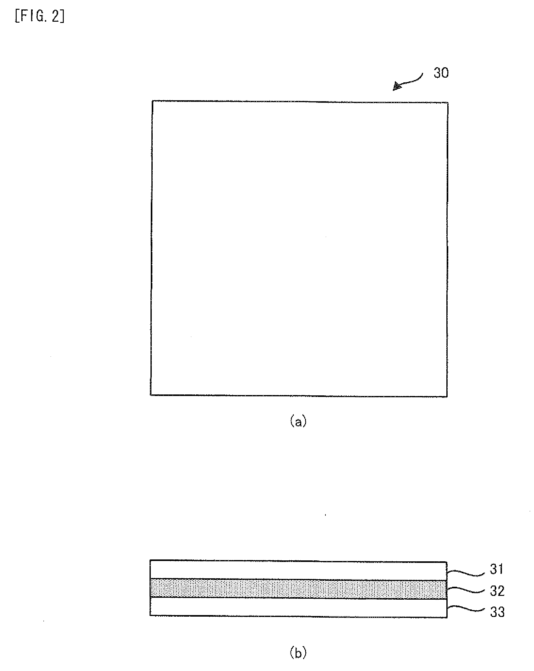
[0080]Firstly, with reference to FIG. 1 to FIG. 4, an explanation will be given on an information recording / reproducing apparatus provided with any of the examples of the driving apparatus of the present invention. Incidentally, here, an explanation will be given on a ferroelectric recording / reproducing apparatus which performs a recording operation or reproduction operation on a recording medium 30 in which a ferroelectric substance is used as a recording material.

[0081](1-1) Structure

[0082]Firstly, the structure of a ferroelectric recording / reproducing apparatus in the example will be explained with reference to FIG. 1. FIG. 1 is a block diagram conceptually showing the structure of a ferroelectric recording / reproducing apparatus in example.

[0083]As shown in FIG. 1, a ferroelectric recording / reproducing ...


PUM


Abstract

A driver (100f) comprises a base section (110), a movable stage section (130) for mounting a driven article (12), a resilient section (12) for connecting the base section and the stage section and exhibiting resiliency for moving the stage section along one direction (Y axis), and a section (161, 162, 22) which applies a shaking force to the resilient section in order to move the stage section to oscillate alone the one direction at a resonance frequency determined by the stage section and the resilient section.

Description

TECHNICAL FIELD[0001]The present invention relates to a driving apparatus for driving a probe or the like in a uniaxial direction or biaxial directions so that the probe scans the surface or the like of a medium.BACKGROUND ART[0002]For example, the development of a probe memory has been advanced which records data onto a recording medium or which reproduces the data recorded on the recording medium by displacing a probe array including a plurality of probes along a recording surface of the recording medium. In such a probe memory, the location of the probe array with respect to the recording medium (in other words, a position relation between the probe array and the recording medium) is determined, for example, by displacing a stage provided with the probe array. In other words, the location of the probe array with respect to the recording medium is determined by the operations of a MEMS (Micro Electro Mechanical System) actuator which is provided with the stage and which can displa...

Claims


Application Information

Patent Timeline
Patent Type & Authority Applications(United States)
IPC IPC(8): H02N2/04H02K41/02H02N11/00
CPCB82Y10/00G11B9/1436G11B9/02
Inventor SZUKI, JUN
Owner PIONEER CORP
Why Eureka
Try Eureka