
Method of imaging a sample using an electron microscope

a technology of electron microscope and sample, which is applied in the direction of instruments, measuring devices, electric discharge tubes, etc., can solve the problems of limited read-out speed of the camera, deterioration of biological samples, and time-consuming process of tilt series acquisition, so as to increase the image portion of the sample

Active Publication Date: 2020-05-28
FEI CO
View PDF0 Cites 0 Cited by
  • Summary
  • Abstract
  • Description
  • Claims
  • Application Information

AI Technical Summary

Benefits of technology

The patent describes a method for imaging a sample by tilting it and changing its position while acquiring images. This method allows for faster acquisition and more information about the sample. It also uses stroboscopic illumination and applies shift and rotational correction to the images. The programmable controller controls the sample holder and camera system to ensure the sample is tilted and positioned correctly for each image. The technical effects of this method include faster acquisition times, more information about the sample, and improved image quality.

Problems solved by technology

As a result of this the acquisition of a tilt series is a time consuming process.
In this respect, it is known that especially biological samples deteriorate due to radiation damage resulting from electron irradiation.
The read-out speed of the camera can be limited by the possibilities of the camera, or by the need for a sufficient number of electrons in one image.
In practice, however, the read-out speed of the camera is the limiting factor.

Method used


Image

  • Method of imaging a sample using an electron microscope
  • Method of imaging a sample using an electron microscope
  • Method of imaging a sample using an electron microscope

Examples


Embodiment Construction

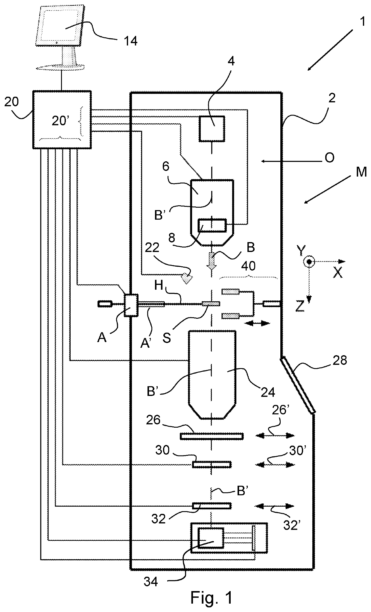
[0040]FIG. 1 (not to scale) is a highly schematic depiction of an embodiment of a charged-particle microscope M according to an embodiment of the invention. More specifically, it shows an embodiment of a transmission-type microscope M, which, in this case, is a TEM / STEM. It is noted that, in the context of the current invention, it could just as validly be a SEM, or an ion-based microscope, for example.

[0041]In FIG. 1, within a vacuum enclosure 2, an electron source 4 produces a beam B of electrons that propagates along an electron-optical axis B′ and traverses an electron-optical illuminator 6, serving to direct / focus the electrons onto a chosen part of a specimen S (which may, for example, be (locally) thinned / planarized). Also depicted is a deflector 8, which can be used to effect scanning motion of the beam B.

[0042]The specimen S is held on a specimen holder H that can be positioned in multiple degrees of freedom by a positioning device / stage A, which moves a cradle A′ onto whic...


PUM


Abstract

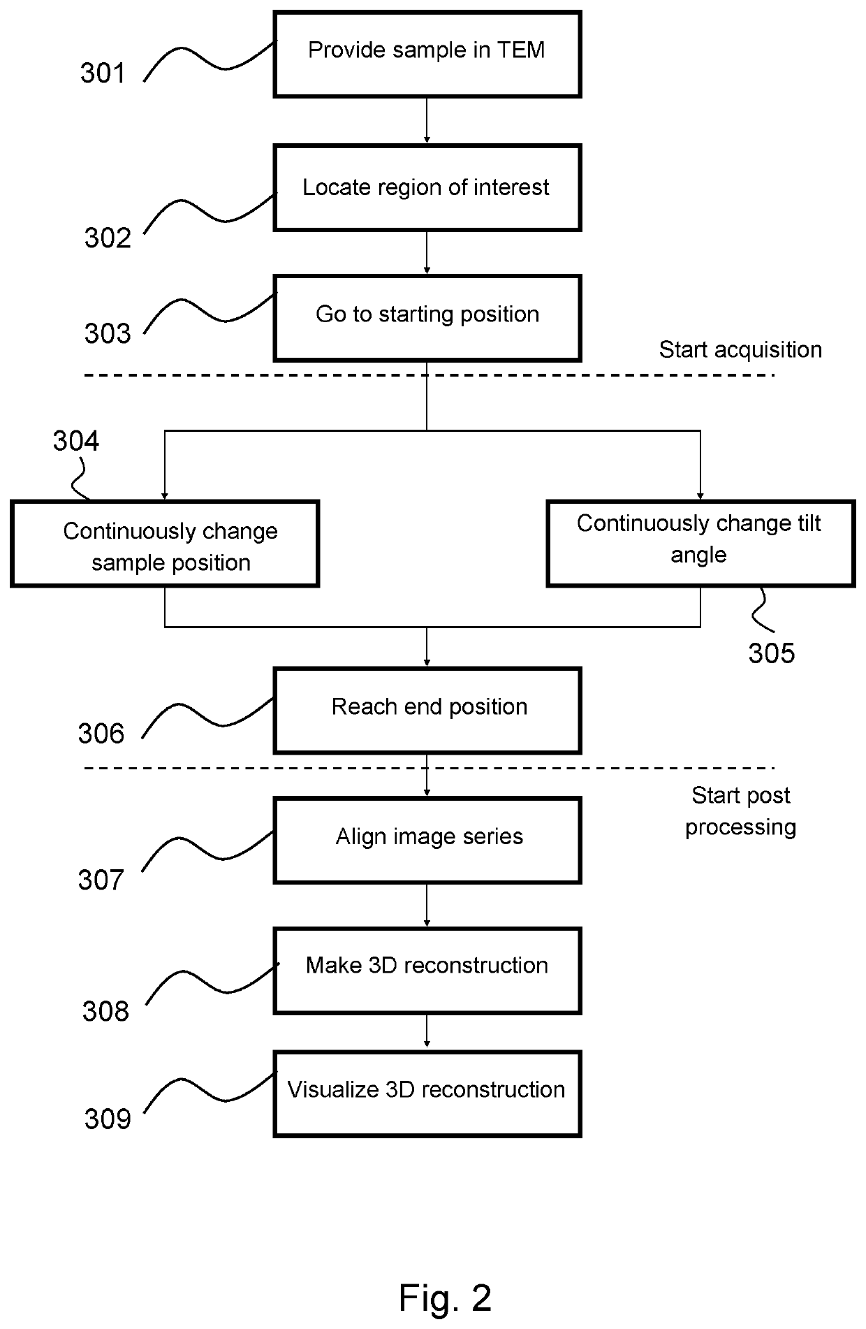
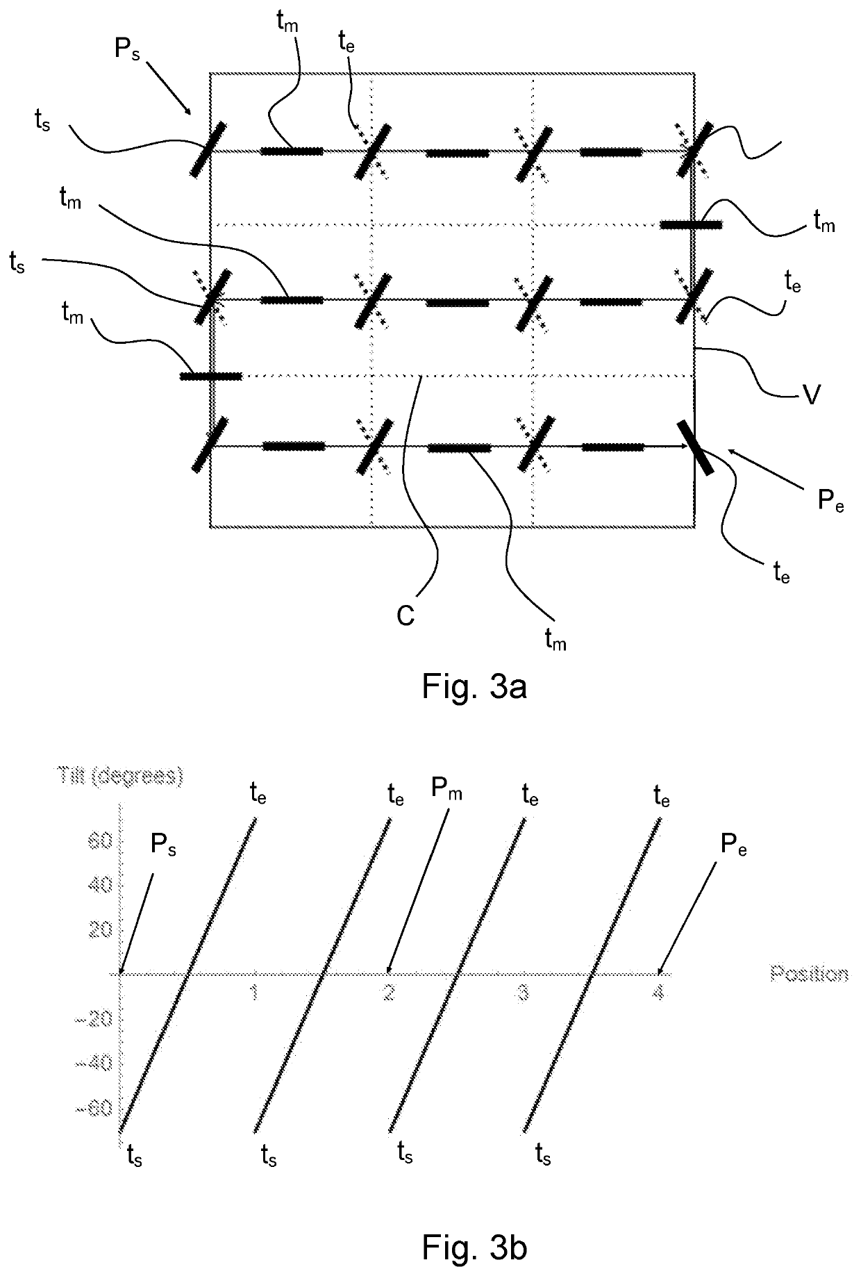
The invention relates to a method of imaging a sample, said sample mounted on a sample holder in an electron microscope, the electron microscope comprising an electron source for generating a beam of energetic electrons along an optical axis and optical elements for focusing and deflecting the beam so as to irradiate the sample with a beam of electrons. The sample holder is capable of positioning and tilting the sample with respect to the electron beam. The method comprises the step of acquiring a tilt series of images by irradiating the sample with the beam of electrons, and concurrently changing a position of the sample during acquisition of the images, so that each image is acquired at an associated unique tilt angle and an associated unique position.

Description

FIELD OF THE INVENTION[0001]The invention relates to a method of imaging a sample using an electron microscope.BACKGROUND OF THE INVENTION[0002]An example of such a method is known from “Technical note: Functional description of Tecnai™ Tomography Software” FEI Company, version 31 Dec. 2003.[0003]In an electron microscope, such as a Transmission Electron Microscope (TEM) an electron source produces a beam of energetic electrons with a selectable energy of, for example, between 80-300 keV, although higher and lower energies are known to be used. This beam is manipulated (focused, deflected) by optical elements (electron lenses, deflectors, multipoles) and irradiates a sample placed in a sample holder. The sample holder positions the sample, the holder typically showing three translational degrees of freedom (x, y, z) and one rotational degree of freedom (α) or more rotational degrees of freedom. The sample is sufficiently thin to be transparent to electrons: some electrons are absorb...

Claims


Application Information

Patent Timeline
Patent Type & Authority Applications(United States)
IPC IPC(8): H01J37/20H01J37/26H01J37/22
CPCH01J2237/20207H01J37/222H01J37/20H01J37/26H01J37/28G01N23/046G01N23/2251G01N2223/03G01N2223/09G01N2223/102G01N2223/33H01J2237/20221H01J2237/2802
Inventor FRANKEN, ERIK MICHIELSCHOENMAKERS, REMCOJANSSEN, BART JOZEFVERHEIJEN, MARTINKOHR, HOLGERDENG, YUCHENVOIGT, ANDREAS
Owner FEI CO
Learn More