System and method for quantum based information transfer

a technology of information transfer and quantum information, applied in the field of system and method for quantum based information transfer, can solve problems such as l and r atomic ensembles becoming enmeshed

Active Publication Date: 2015-02-26
US SEC THE ARMY THE
View PDF1 Cites 95 Cited by
  • Summary
  • Abstract
  • Description
  • Claims
  • Application Information

AI Technical Summary

Problems solved by technology

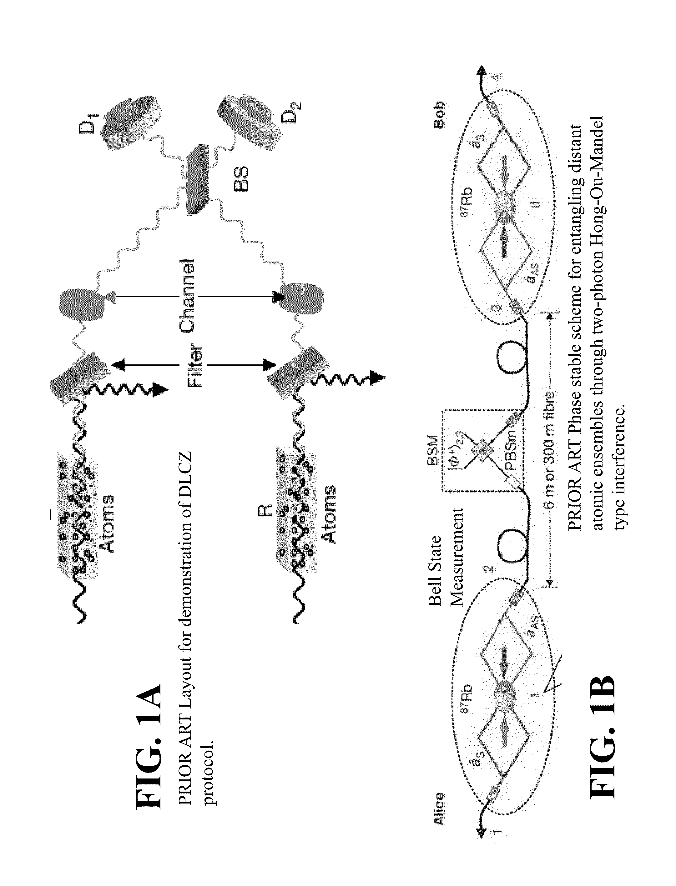
These optical fields 1 and 2 interfere on a Beam Splitter BS resulting in L and R atomic ensembles becoming entangled.

Method used


Image

  • System and method for quantum based information transfer
  • System and method for quantum based information transfer
  • System and method for quantum based information transfer

Examples


example

Sound Spectrum Computation

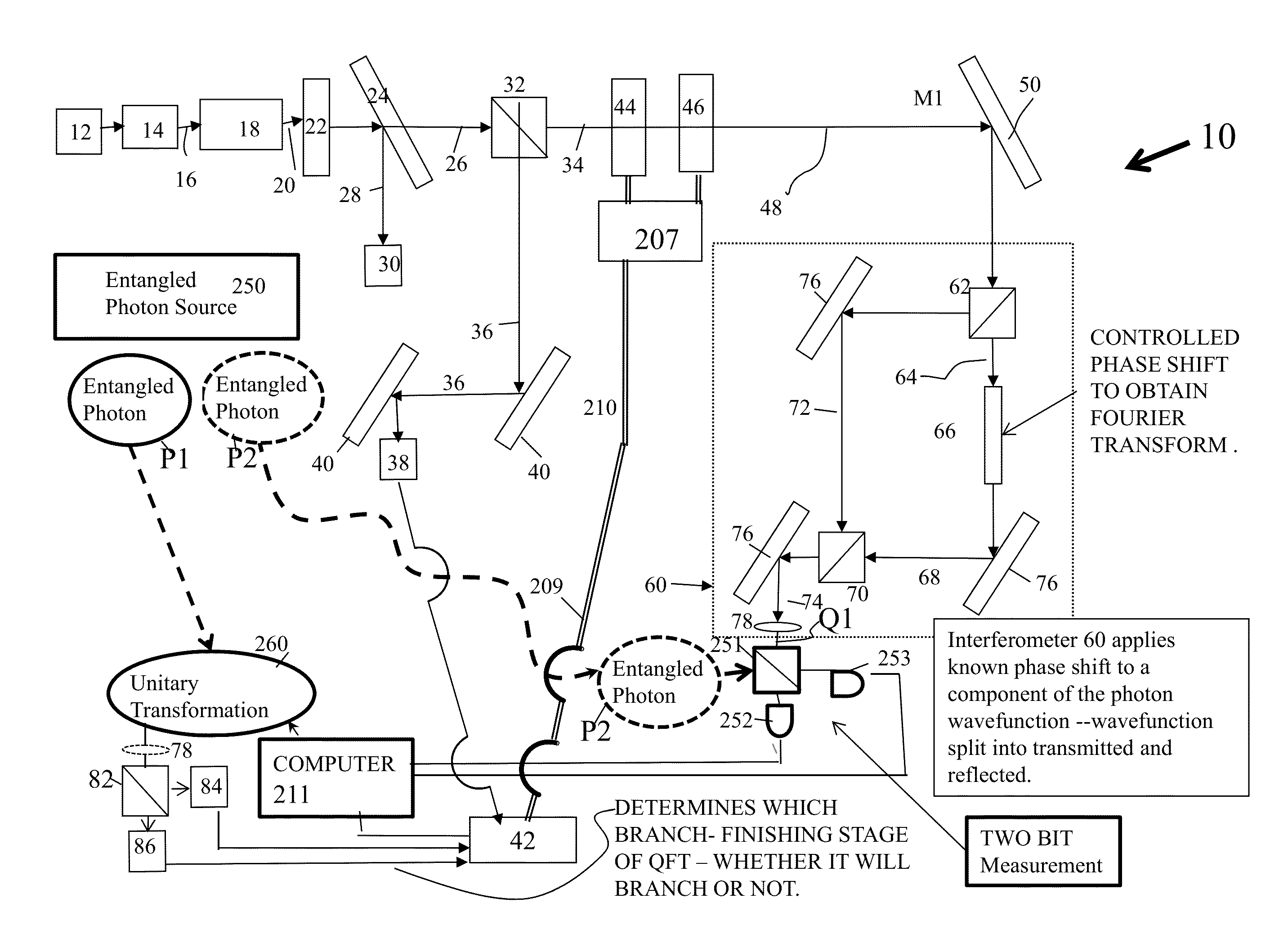
[0120]In order to evaluate the ability of the inventive quantum algorithm to compress and transmit a signal representative of the data set with a comparatively small number of photons, 32 sound samples defining a normalized arbitrary spectrum are provided in the top left panel of FIG. 9. The histogram defines a quantized spectrum while the solid lines superimposed thereover represent classical Fourier (gray line) transform and QFT (black line) fits to the data. The 32 sound sample elements of the top left spectrum are amenable to storage and operation on 2n or 4 qubits. The top right panel of FIG. 9 represents a single statistical evaluation of the arbitrary spectrum depicted in the top left panel. The line superimpositions on the histogram in the top right represents a classical and quantum magnitude superposition. The lower left panel is duplicative of the conventional four photon single evaluation of the arbitrary spectrum (upper left panel) and represen...


PUM


Abstract

A system for communicating data comprising sender and receiver subsystems; at least one data input; at least one entangled photon source; first photons of the pairs of entangled photons outputted by the at least one photon source being processed by one of the sender or receiver subsystem; second photons of the pairs of entangled photons being processed by the other of the sender or receiver subsystem; a photonic element configured to receive the first photons of the pairs of entangled photons and enable interference therebetween; at least one absorber configured to absorb the first photons after passage through the beam splitter, the absorbance of the first photons operating to transfer the properties of the entanglement to the second photons of the pairs of entangled photons; and a Bell state measurement element operatively associated with the receiver subsystem configured to measure the second photons of the pairs of entangled photons.

Description

CROSS REFERENCE TO RELATED APPLICATIONS[0001]This application claims priority to and the benefit of U.S. patent application Ser. No. 13 / 948,660 (ARL 04-62CIP2), filed Jul. 23, 2013 by Ronald E. Meyers and Keith S. Deacon, entitled Quantum Based Information Transfer System And Method,” which is a continuation-in-part of and claims priority to application Ser. No. 12 / 705,566 (ARL 04-62 CIP), entitled “Quantum Based Information Transmission System and Method,” filed Feb. 12, 2010, which issued as U.S. Pat. No. 8,503,885 on Aug. 6, 2013, by Ronald E. Meyers and Keith S. Deacon the inventors herein, which in turn claims priority to U.S. application Ser. No. 11 / 196,738 (ARL 04-62), filed Aug. 4, 2005, which issued as U.S. Pat. No. 7,660,533 on Feb. 9, 2010, by Ronald E. Meyers and Keith S. Deacon, and U.S. Provisional Patent Application Ser. No. 60 / 598,537 filed Aug. 4, 2004, all four of which are incorporated herein by reference.GOVERNMENT INTEREST[0002]The invention described herein may...

Claims


Application Information

Patent Timeline
Patent Type & Authority Applications(United States)
IPC IPC(8): H04B10/70H04B10/60H04B10/50
CPCH04B10/70H04B10/60H04B10/50B82Y10/00B82Y20/00G06N10/00H04L9/0855Y10S977/933
Inventor MEYERS, RONALD E.DEACON, KEITH S.
Owner US SEC THE ARMY THE
Why Eureka
Try Eureka