Hyper-Entangled Photon Server System and Associated Methods

a photon server and hyper-entangled technology, applied in the direction of optical radiation measurement, instruments, computing models, etc., can solve the problems of random frequency measurement, and loss of useful polarization entanglement, and replace less useful frequency entanglemen

Active Publication Date: 2018-08-23
GOVERNMENT OF THE UNITED STATES AS REPRESENTED BY THE SEC OF THE AIR FORCE
View PDF0 Cites 14 Cited by
  • Summary
  • Abstract
  • Description
  • Claims
  • Application Information

AI Technical Summary

Benefits of technology

[0019]With the above in mind, embodiments of the present invention are directed to a method for creating measurements of photons at distinct locations, comprising receiving, using a non-polarizing beam splitter (BS), electromagnetic (EM) radiation comprising a hyperentangled photon pair, defined as a first photon and a second photon entangled in a plurality of degrees of freedom including polarization, frequency, and path, wherein frequency is non-degenerate, spatially separating, using the BS, output probability amplitudes for the non-degenerate frequencies of the hyperentangled photon pair into a first set of anti-bunched rotationally invariant amplitude states and a second set of bunched rotationally invariant amplitude states, and rotating, using a first Lyot filter, the respective polarization of incongruent frequency states in the first set of anti-bunched rotationally invariant amplitude states, to define a first set of anti-bunched non-rotationally invariant amplitude states. The method may further comprise preserving, using the first ...

Problems solved by technology

Eavesdroppers will be wrong a discernable fraction of the time, alerting legitimate users of their intrusion.
In other words, the frequency degree of freedom is not as intrinsically secure as polarization degrees of freedom for random number generation utili...

Method used


Image

  • Hyper-Entangled Photon Server System and Associated Methods
  • Hyper-Entangled Photon Server System and Associated Methods
  • Hyper-Entangled Photon Server System and Associated Methods

Examples


Embodiment Construction

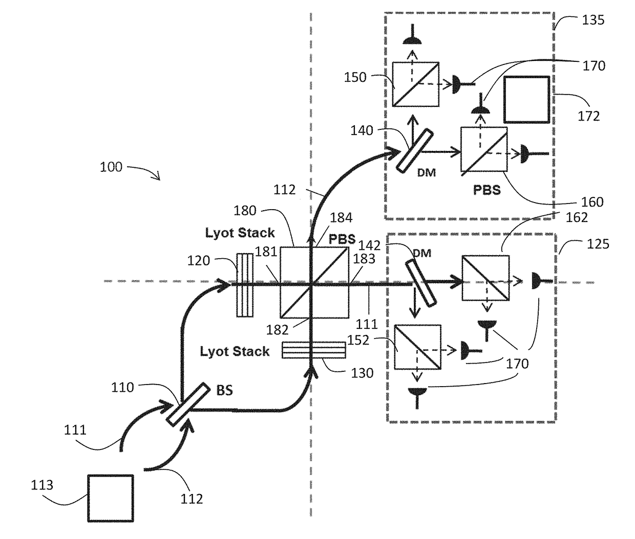
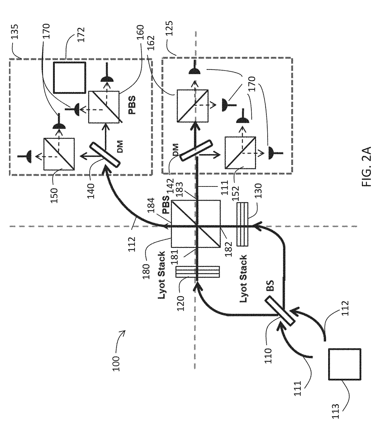
[0039]The present invention will now be described more fully hereinafter with reference to the accompanying drawings, in which preferred embodiments of the invention are shown. This invention may, however, be embodied in many different forms and should not be construed as limited to the embodiments set forth herein. Rather, these embodiments are provided so that this disclosure will be thorough and complete, and will fully convey the scope of the invention to those skilled in the art. Those of ordinary skill in the art realize that the following descriptions of the embodiments of the present invention are illustrative and are not intended to be limiting in any way. Other embodiments of the present invention will readily suggest themselves to such skilled persons having the benefit of this disclosure. Like numbers refer to like elements throughout.

[0040]In this detailed description of the present invention, a person skilled in the art should note that directional terms, such as “abov...


PUM


Abstract

A hyper-entanglement photon server (i.e., hub) employs non-degenerate frequencies input as entangled photon pairs into a beam splitter. The beam splitter splits probability amplitudes into two sets of bunched superposition states plus two sets of anti-bunched superposition states. The amplitudes pass through identical Lyot filters and then either enter a polarization beam splitter, where the bunched and anti-bunched states switch identities, or merely advance unchanged to awaiting users at two distinct and spatially-displaced positions (i.e., spokes). The Lyot filters change the output amplitudes from rotationally invariant superpositions of generalized Bell States to rotationally non-invariant superpositions of generalized Bell states. All hubs and spokes pre-share operating key material (a security method called KCQ) that may be continually updated by shared stream ciphers seeded by fresh key material engendered by hub-to-spoke quantum communication.

Description

CROSS REFERENCE TO RELATED APPLICATIONS[0001]This application claims the benefit under 35 U.S.C. § 119(e) of U.S. Provisional Patent Application Ser. No. 62 / 462,062 filed on Feb. 22, 2017 and titled Quantum Operations On Entangled Photons Using Lyot Filters, the entire content of which is incorporated herein by reference.GOVERNMENT INTEREST[0002]The invention described herein may be manufactured and used by or for the Government of the United States for all governmental purposes without the payment of any royalty.FIELD OF THE INVENTION[0003]The present invention relates to the architecture and operation of a secure communication system. More specifically, this invention pertains to devices, systems, and methods for securing free space laser communications applications such as seeding stream ciphers encrypting sensitive data.BACKGROUND OF THE INVENTION[0004]This invention passively operates on bi-partite input entangled photon pairs for distribution by a server hub to several receive...

Claims


Application Information

Patent Timeline
IPC IPC(8): H04B10/85H04L9/06G06N99/00H04B10/70G01J4/02
CPCH04B10/85H04L9/0618G06N99/002H04B10/70G01J4/02G02B27/288G02B27/283G02B27/141G09C1/00H04L9/0855G06N10/00
Inventor HUGHES, DAVID H.ERDMANN, REINHARD K.
Owner GOVERNMENT OF THE UNITED STATES AS REPRESENTED BY THE SEC OF THE AIR FORCE
Why Eureka
Try Eureka