
System for Managing a Cleanroom Environment

a cleanroom environment and management system technology, applied in space heating and ventilation control systems, lighting and heating equipment, heating types, etc., can solve problems such as contamination or defect, internal source of contamination of clean room workforce, cracks,

Inactive Publication Date: 2015-02-26
CHIEN ANTHONY
View PDF3 Cites 31 Cited by
  • Summary
  • Abstract
  • Description
  • Claims
  • Application Information

AI Technical Summary

Benefits of technology

This patent is a system that helps manage cleanroom resources by integrating several critical features into a low-cost package. The system includes a way to turn off air conditioning units and lighting when they are not needed, which saves energy. This helps to create a more efficient and cost-effective cleanroom.

Problems solved by technology

Also, external contamination can infiltrate through building doors, windows, cracks, and wall penetrations for pipes, cables and ducts.
The largest potential internal source of contamination is the clean room workforce.
The greatest concern is that a particle deposits on the product causing contamination or defect.
Although the large cleanrooms used in semiconductor manufacturing operations are typically used 24 hours per day, 7 days per week, it is not uncommon for small and mid-sized cleanrooms operated in other industries to be unused at night and on weekends, although the cleanroom systems typically remain in operation to prevent particulate contamination during the off hours.

Method used


Image

  • System for Managing a Cleanroom Environment
  • System for Managing a Cleanroom Environment
  • System for Managing a Cleanroom Environment

Examples


Embodiment Construction

[0029]The features of the present invention are set forth in the appended claims which may be best understood by reference to the following description taken in conjunction with the accompanying drawings.

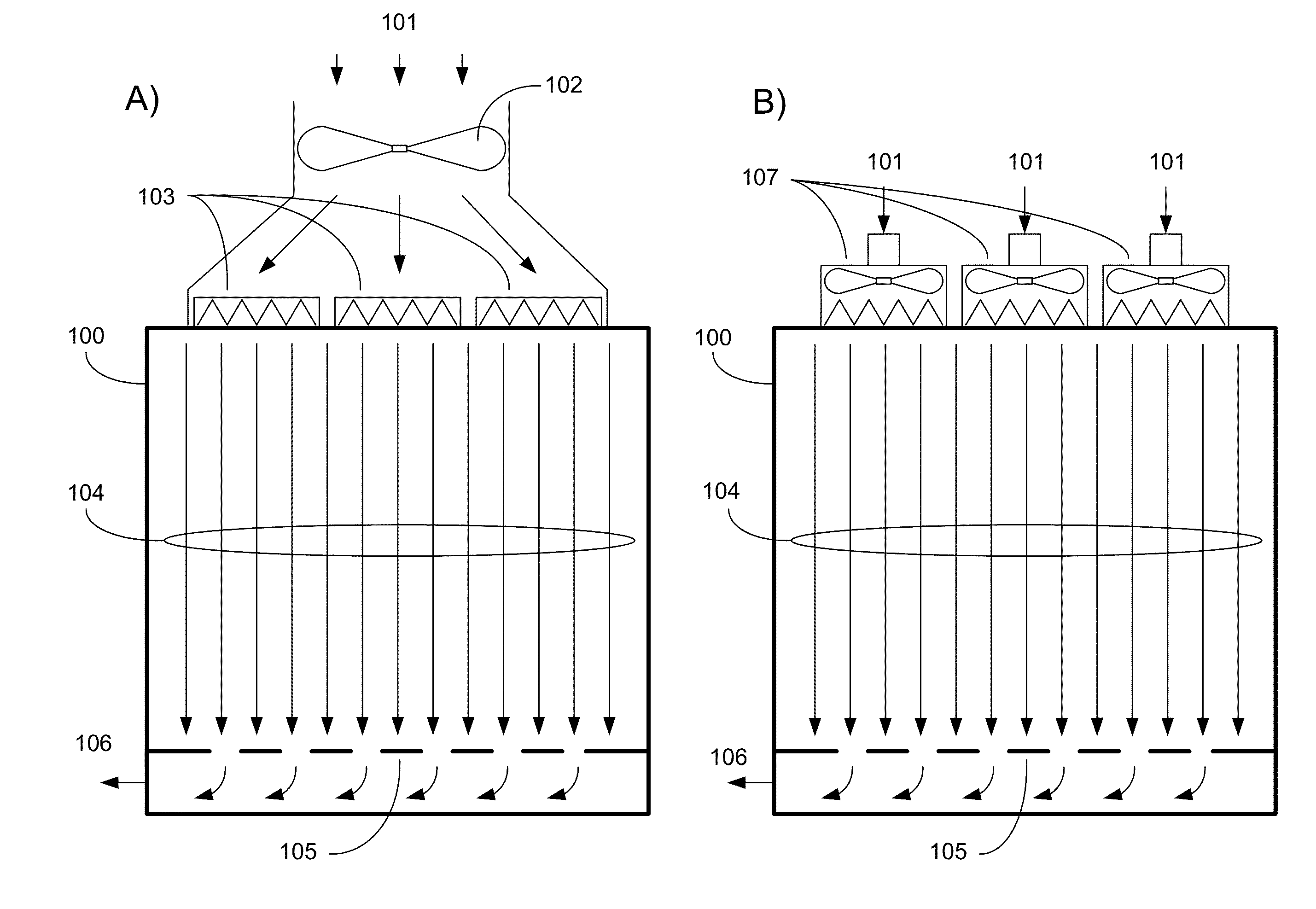
[0030]Cleanrooms have evolved into two major types differentiated by their method of ventilation: unidirectional airflow and non-unidirectional airflow cleanrooms. Unidirectional airflow cleanrooms are characterized by a design that attempts to maintain airflow at a constant level throughout the cleanroom. In non-unidirectional airflow cleanrooms, the airflow is constant only over a limited work area within the cleanroom, and is allowed to diminish elsewhere within the cleanroom. Unidirectional airflow cleanrooms are generally required to achieve the lowest cleanroom classes. FIG. 1 depicts the two basic configurations used to achieve unidirectional airflow cleanrooms. FIG. 1A shows a cleanroom 100 wherein conditioned air 101 is pressurized by a single large fan 102 and is directed ...


PUM


Abstract

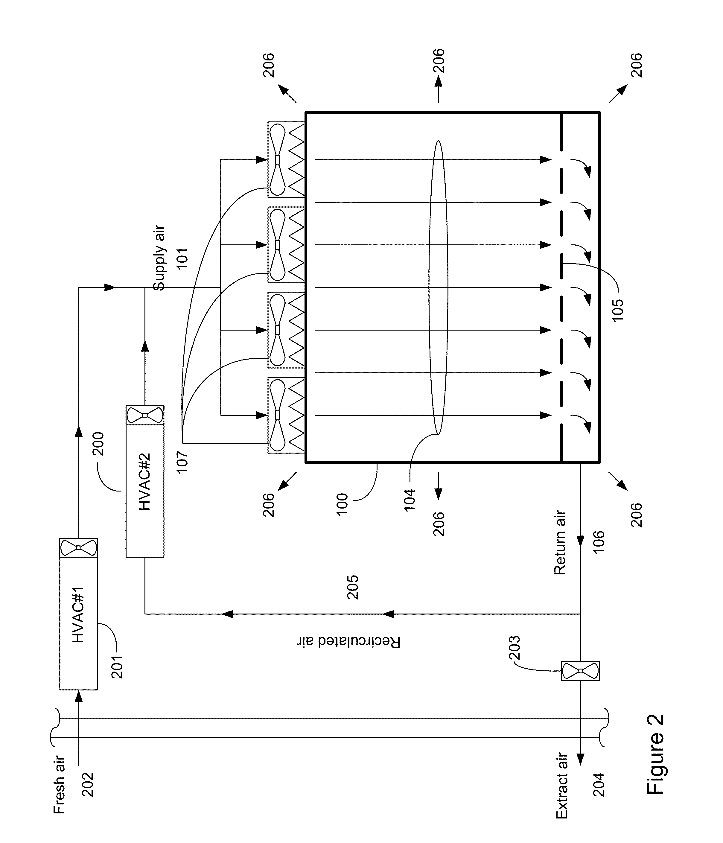
A system for managing cleanroom resources by providing a number of critical features in an integrated, low-cost package is described. The critical features include monitoring and recording cleanroom environmental conditions such as temperature, humidity and room differential pressure, notifying users of alarm situations when cleanroom environmental conditions fall outside predetermined limits, and reducing cleanroom energy usage by turning off HEPA filter fan units (FFUs) and cleanroom lights when they are not needed.

Description

CROSS REFERENCE TO RELATED APPLICATIONS[0001]This application claims priority to Provisional application 61 / 870,159 filed 26 Aug. 2013 which is incorporated herein by reference in its entirety.BACKGROUND OF THE INVENTION[0002]1. Technical Field[0003]The present invention relates to means for monitoring and recording cleanroom environmental conditions while providing warning messages in various formats if the environmental parameters depart from preset limits. The system also provides a means for optimizing cleanroom energy consumption.[0004]2. Related Background Art[0005]Cleanrooms are specially constructed, environmentally controlled enclosed spaces where extensive measures are taken to eliminate airborne particulates. Cleanrooms may also exhibit tight controls on temperature, humidity, air pressure, airflow patterns, air motion, vibration, noise, viable (living) organisms, and lighting, but the primary design objective of a cleanroom is particulate control. The term “particulate c...

Claims


Application Information

Patent Timeline
Patent Type & Authority Applications(United States)
IPC IPC(8): F24F3/16F24F11/00
CPCF24F3/161F24F11/0001F24F11/0012F24F11/0015F24F11/30F24F2110/10F24F2110/20F24F11/61F24F11/46F24F11/77F24F11/64F24F11/526F24F11/52
Inventor CHIEN, ANTHONY
Owner CHIEN ANTHONY
Learn More