Miniaturized scanning system

a scanning system and scanning technology, applied in the field of miniaturized scanning system, can solve the problems of long time, difficult to obtain this precision, manual sweeping may not provide the smoothness of motion with minimal, etc., and achieve the effect of reproducibility, smooth motion of the end, and preservation of scanning accuracy

Active Publication Date: 2015-02-26
MAUNA KEA TECHNOLOGIES +3
View PDF0 Cites 23 Cited by
  • Summary
  • Abstract
  • Description
  • Claims
  • Application Information

AI Technical Summary

Benefits of technology

[0013]2D motion of the end of the flexible device can thus be obtained, possibly by actuation motors, for example electrical motors, located at a proximal part of the medical tool, i.e. apart from the part intended to intrude in th...

Problems solved by technology

With manual sweeping, it is difficult to obtain this precision for such a long time.
Further, manual sweeping may not provide the smoothness of the motion with minimal accelerations and/or changes of directions wh...

Method used


Image

  • Miniaturized scanning system
  • Miniaturized scanning system
  • Miniaturized scanning system

Examples


Embodiment Construction

[0053]Specific embodiments of the present disclosure will now be described in detail with reference to the accompanying Figures. Like elements in the various Figures may be denoted by like numerals. Embodiments of the present disclosure relate to a miniaturized scanning system to generate movement of a flexible device positioned at a distal part of a medical tool and a robotized device comprising said miniaturized scanning system.

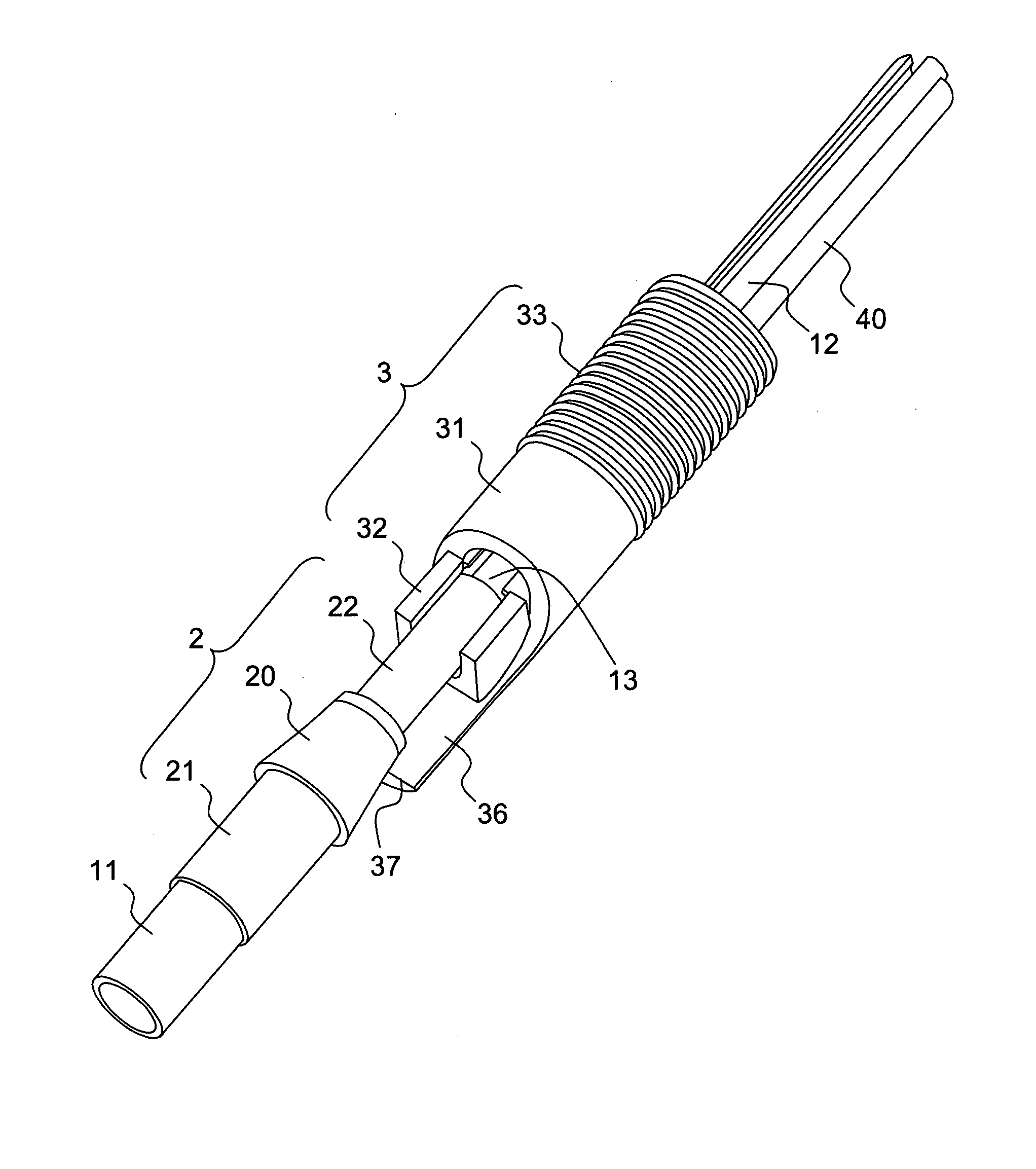
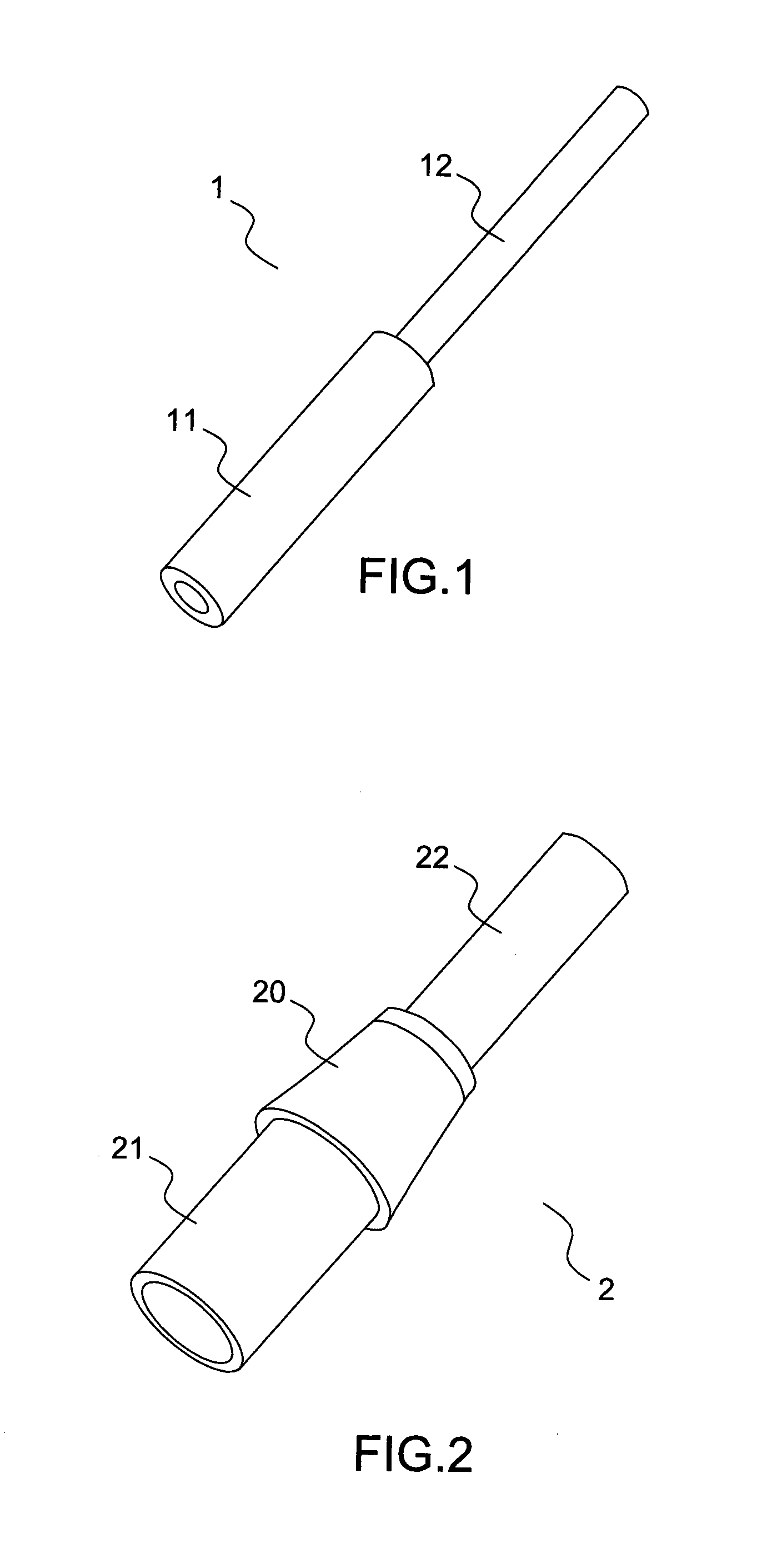
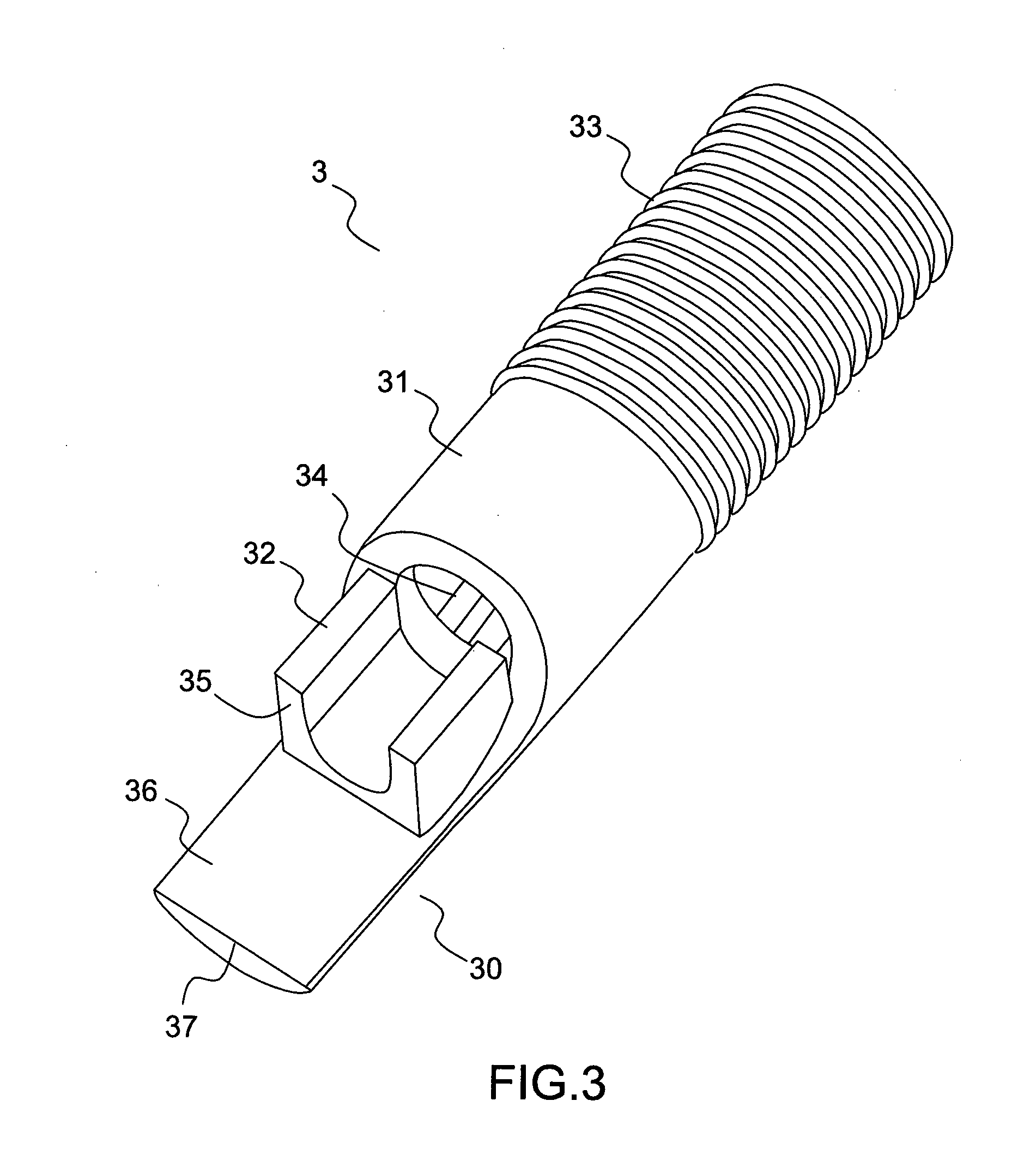
[0054]FIGS. 2 to 5 represent different pieces of a miniaturized scanning system shown in FIG. 6 and adapted to generate 2D movement of an optical head 11 of an optical probe 1, an embodiment of which is shown in FIG. 1.

[0055]The optical probe 1 as shown in FIG. 1 comprises the optical head 11 which houses one or a plurality of optical lenses and the fiber cable 12 which is a flexible portion of the optical probe 1. The optical probe is for example the distal part of a fibered confocal microscope as shown in FIG. 11. The optical head 11 is typically of 2.6 m...


PUM


Abstract

A miniaturized scanning system to generate movement of a flexible device positioned at a distal part of a medical tool. The miniaturized scanning system includes an inner shaft with a longitudinal axis, adapted to guide said flexible device along the longitudinal axis, an abutment comprising an external surface and adapted to maintain said device, and a pusher mechanism adapted to engage with said abutment. The miniaturized scanning system includes at least one end portion adapted to contact said external surface of the abutment at a contact point, wherein said end portion is configured to translate along said longitudinal axis of the inner shaft and wherein the translation of said end portion results in a bending of the device in a bending plane defined by the longitudinal axis of the inner shaft and said contact point.

Description

BACKGROUND[0001]1. Field of the of the Present Disclosure[0002]The disclosure relates to a miniaturized scanning system to generate 2D movement of a distal part of a medical tool.[0003]2. Background Art[0004]The Applicant has developed a confocal imaging system based on a fiber bundle probe for in vivo in situ imaging of biological tissues as described for example in US Patent Application 2005 / 0242298 which is fully incorporated herein by reference. Such a system, also referred as a fibered confocal microscope, is for example represented schematically on FIG. 11. A laser 140 is scanned over a proximal face 112 of a fiber bundle probe 110 which is connected to a light injection module 130 via an abutment 120. The light injection module 130 comprises an objective ensuring that light from the laser is properly injected into each fiber of the fiber bundle probe. Scanning the proximal face of the fiber bundle results in a fiber per fiber injection of light and, at a distal end of the bun...

Claims


Application Information

Patent Timeline
IPC IPC(8): A61B1/005A61B1/00
CPCA61B1/0057A61B1/00172A61B1/00165A61B1/00133A61B5/0062A61B5/0068A61B5/0084G02B2006/0098G02B6/0008G02B6/04
Inventor ERDEN, MUSTAFA SUPHIROSA, BENOITSZEWCZYK, JEROMEMOREL, GUILLAUMEVIDAL, CLEMENTHENRI, PATRICKBOULAROT, NICOLAS
Owner MAUNA KEA TECHNOLOGIES
Why Eureka
Try Eureka