Pulmonary Compliance and Air Flow Resistance

Inactive Publication Date: 2015-02-26
ECHOSENSE JERSEY LTD +1
View PDF16 Cites 3 Cited by
  • Summary
  • Abstract
  • Description
  • Claims
  • Application Information

AI Technical Summary

Benefits of technology

[0011]In some embodiments, the method further comprises the steps of: (d) modifying the gas-flow path to have a second resistance value; (e) receiving, when the output port is closed and a patient is blowing into the gas inlet so as to maintain a second given pressure relatively constant, a measurement of a third pressure from the pressure sensor; (f) receiving, after steps (d) and (e) have been performed, and when the gas output port is opened and the patient is blowing into the gas inlet so as to maintain the second given pressure relatively constant, a measurement of a fourth pressure from the pressure sensor and a measurement of a second gas flow from the gas flow sensor; and (g) computing a second pulmonary flow resistance based upon the measurement of the third pressure, the measurement of the fourth pressure, the second resistance value, and the measurement of the second gas flow. In some embodiments, the method further comprises the step of: (h) generating a resistance-to-flow curve depicting pulmonary resistance versus pulmonary flow and a resistance-to-pressure curve depicting pulmonary resistance versus pulmonary pressure, by taking measurements at different blowing pressures and/or resistance values.
[0012]The invention, in another aspect, features a method for measuring pulmonary flow resistance. The method comprises the steps of: (a) closing a gas output port of a gas-tight chamber, the chamber having a gas inlet; (b) setting a gas flow resistor disposed in a gas-flow path between the inlet and the outlet port to a first resistance value; (c) receiving, after steps (a) and (b) have been performed and when a patient is blowing into the gas inlet at a given pressure, a measurement of a first pressure in the chamber from a pressure sensor; (d) opening, after step (c) has been performed, the gas output port; (e) receiving, after step (d) has been performed and when the patient is blowing into the gas inlet so as to maintain the given pressure relatively constant, a measurement of a second pressure in the chamber from the pressure sensor and a measurement of a first gas flow through the chamber from a gas flow sensor; and (f) computing a first pulmonary flow resistance based upon the measurement of the first pressure, the measurement of the second pressure, the first resistance value, and the measurement of the first gas flow.
[0013]The invention, in another aspect, features a device for measuring pulmonary flow resistance. The device comprises a housing that defines a gas-tight chamber, the chamber having a gas inlet and a gas output port and a gas-flow path between the gas inlet and the gas output port, wherein the gas output port is configured to switch selectively between (i) an open position in which gas can flow out of the chamber through the gas output port and (ii) a closed position in which gas flow out of the chamber is blocked. The device further comprises a gas flow sensor configured to measure flow of gas through the chamber, a pressure sensor configured to measure pressure in the chamber, and a gas flow resistor disposed in the gas-flow path, configured to be adjustable by a control input. The device further comprises a controller configured to (a) set the gas flow resistor to a first resistance value by sending a first control signal to the control input, (b) receive, when the output port is closed and a patient is blowing into the gas inlet at a given pressure, a measurement of a first pressure from the pressure sensor, (c) receive, after steps (a) an

Problems solved by technology

In a variety of diseases, for example COPD (chronic obstructive pulmonary disease) and specifically emphysema and asthma, the airways are narrowed such that th

Method used


Image

  • Pulmonary Compliance and Air Flow Resistance
  • Pulmonary Compliance and Air Flow Resistance
  • Pulmonary Compliance and Air Flow Resistance

Examples


Embodiment Construction

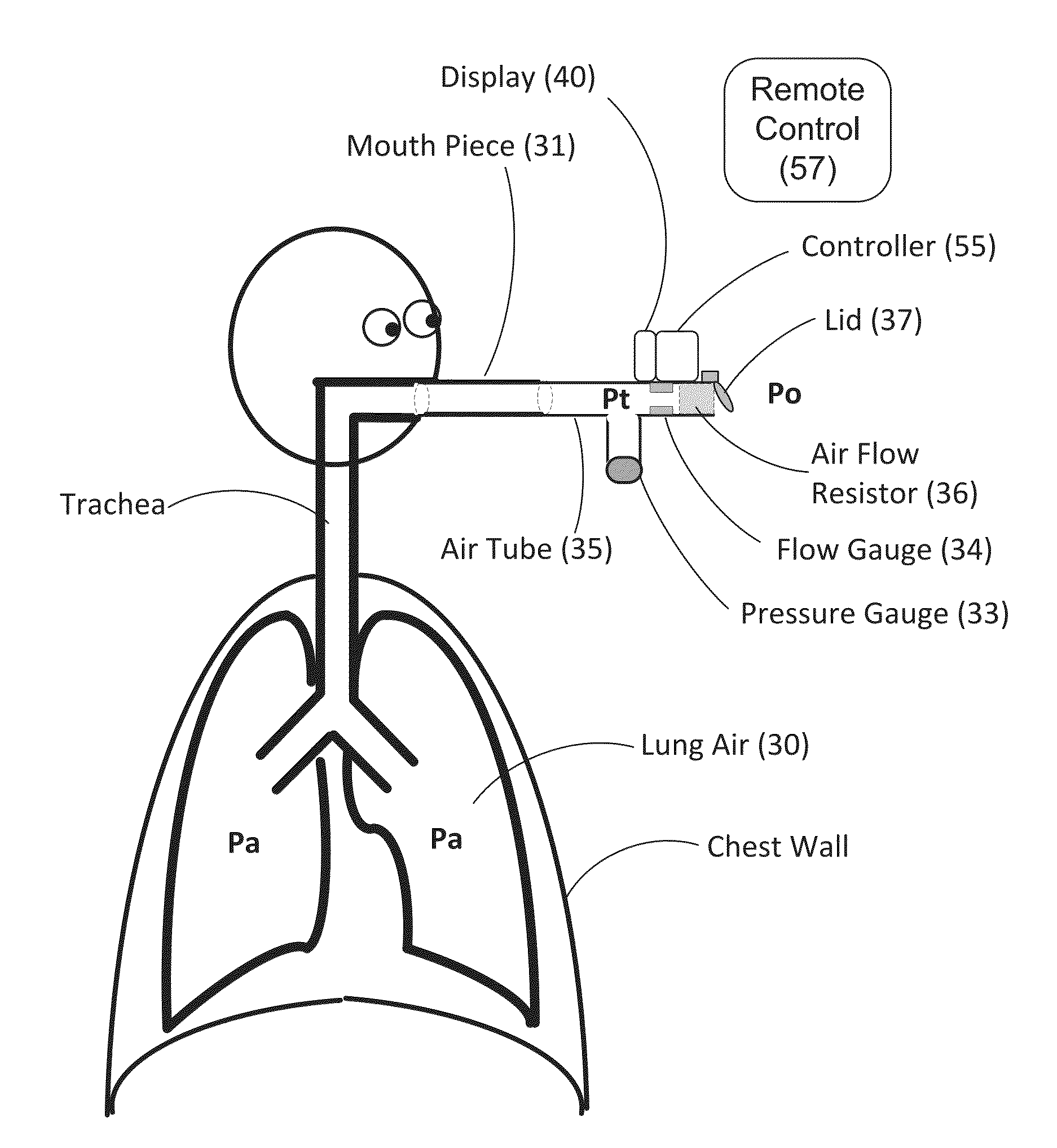
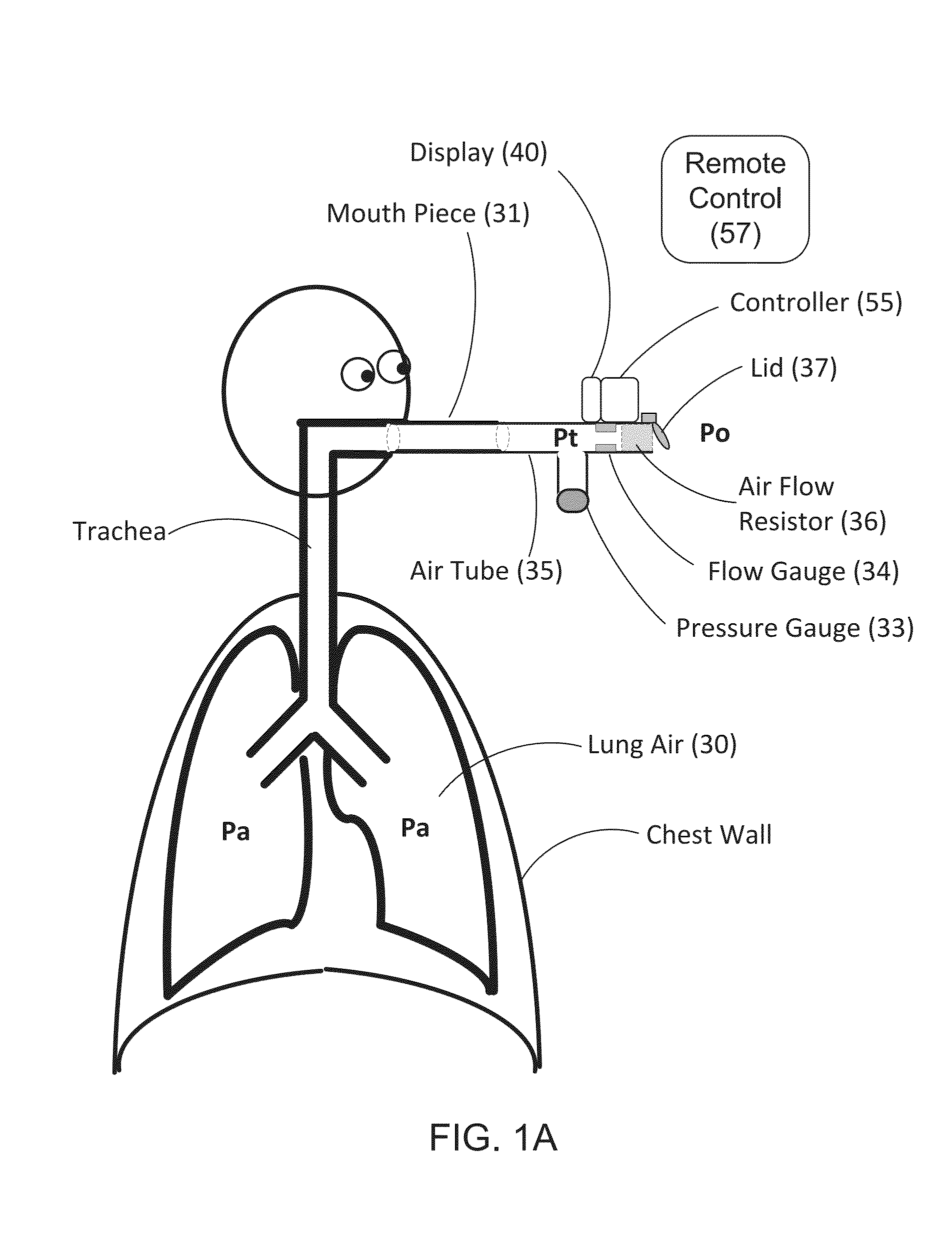
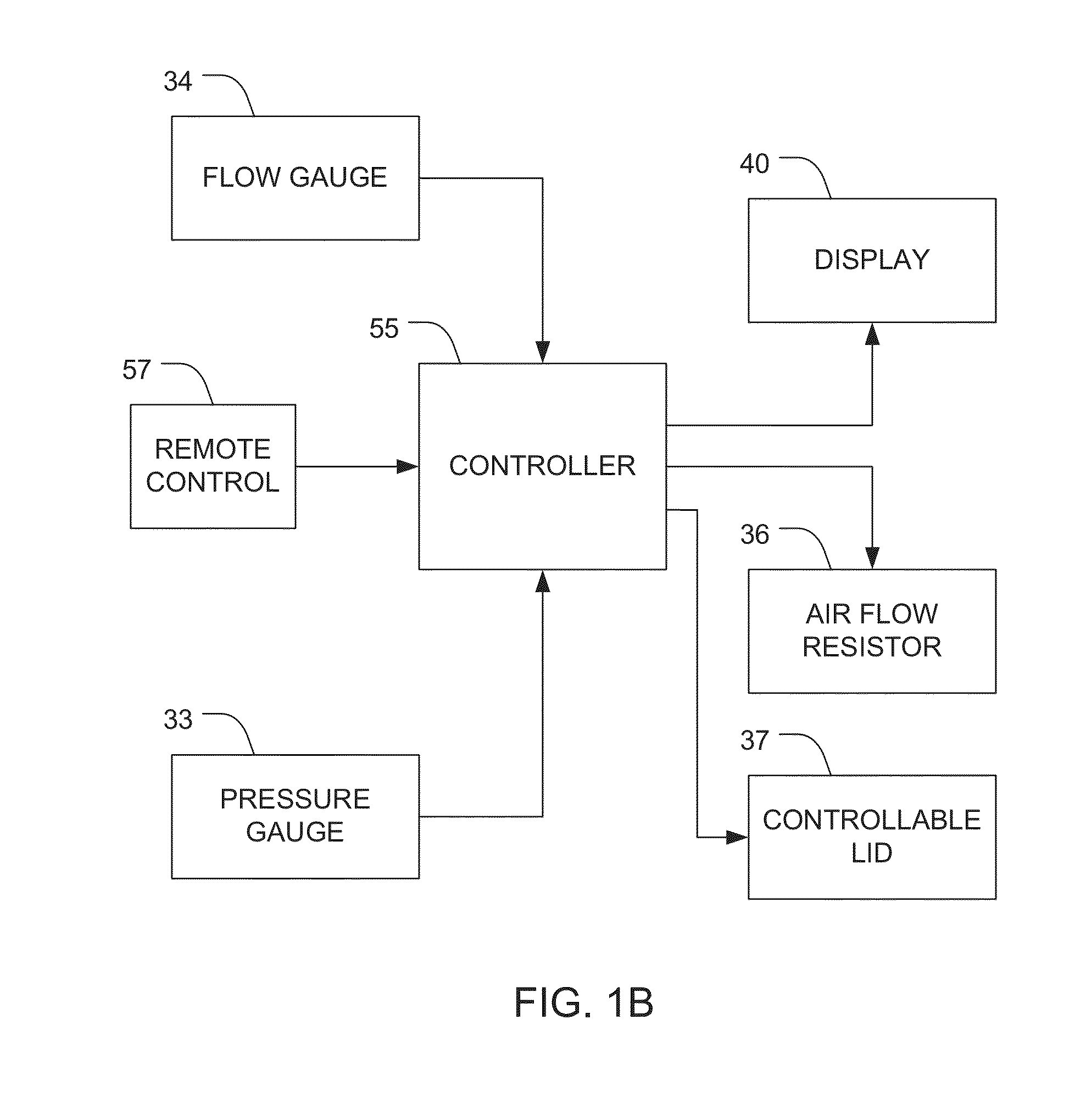
[0023]The Pulmonary Resistance Compliance Gauge (PRCG) is a simple device, which can be hand held, for direct rapid measurement of pulmonary airflow resistance and lung compliance. FIG. 1A is a schematic representation of an embodiment of the various components of the PRCG, and FIG. 1B is a functional block diagram of an embodiment of the PRCG.

[0024]The PRCG includes a housing that defines a gas-tight chamber. One example of a housing is air tube 35. The chamber has a gas inlet and a gas output port. A mouthpiece 35 can optionally be attached to the gas inlet. The gas output port is configured to switch selectively between (a) an open position in which gas can flow out of the chamber through the gas output port and (b) a closed position in which gas flow out of the chamber is blocked. An example gas output port is lid 37 depicted in FIG. 1A. In alternative embodiments the gas output port can also comprise, for example, a flap, shutter, or cap. The gas output port can optionally incl...


PUM


Abstract

Methods and apparatuses are described for direct rapid measurement of pulmonary flow resistance. A measurement of a first pressure in a gas-tight chamber is received from a pressure sensor when a gas output port of the chamber is closed, a patient is blowing into a gas inlet of the chamber at a given pressure, and a gas-flow path between the inlet and output port has a resistance value. A measurement of a second pressure in the chamber is received from the pressure sensor and a measurement of gas flow through the chamber is received from a gas flow sensor when the output port is opened and the patient is blowing into the inlet to maintain the given pressure relatively constant. A pulmonary flow resistance is computed based upon the measurement of the first pressure, the measurement of the second pressure, the resistance value, and the measurement of gas flow.

Description

CROSS REFERENCE TO RELATED APPLICATIONS[0001]This application claims the benefit of U.S. Provisional Patent Application No. 61 / 869,919, filed Aug. 26, 2013, which is incorporated herein by reference.BACKGROUND[0002]Living organisms require oxygen supply and removal of CO2 to maintain their life and activity. In land based animals this is achieved by the respiratory system that pumps air into and out of the lungs and enables the required gas exchange between the inspired air and the circulating blood. In general terms the respiratory process is based on the passage of air through the mouth to the alveoli. Once air progresses through the mouth or nose, it travels through the oropharynx, nasopharynx, the larynx, the trachea, and a progressively subdividing system of bronchi and bronchioles of smaller and smaller diameter until it finally reaches the alveoli where the gas exchange of carbon dioxide and oxygen takes place.[0003]The drawing and expulsion of air (ventilation or breathing) ...

Claims


Application Information

Patent Timeline
IPC IPC(8): A61B5/085
CPCA61B5/085A61B5/087A61B5/091A61B5/097A61B5/7239A61B5/7242
Inventor PALTI, YORAM
Owner ECHOSENSE JERSEY LTD
Why Eureka
Try Eureka