
Method and system for visualizing mechanical ventilation information

a mechanical ventilation and information technology, applied in the field of respiratory care systems, can solve the problems of complex process, difficult control of parameter adjustments, and the increase of complexity of mechanical ventilators

Active Publication Date: 2016-05-03
GENERAL ELECTRIC CO
View PDF13 Cites 2 Cited by
  • Summary
  • Abstract
  • Description
  • Claims
  • Application Information

AI Technical Summary

Benefits of technology

The patent describes a user interface for a medical system that includes a memory to store sensor measurements of a patient and a processor to display a visualization of a patient's tidal volume and lung compliance simultaneously. The user interface can also update the visualization based on changes to the ventilator settings. This technical effect allows medical professionals to better understand the patient's ventilation status and make informed adjustments to the ventilator settings.

Problems solved by technology

These parameter adjustments are challenging to control accurately, particularly using these conventional systems.
With respect to ventilation, this is a complex process of delivering oxygen to, and removing carbon dioxide from, alveoli within patients' lungs.
These mechanical ventilators have become increasingly sophisticated and complex, due in part to enhanced understandings of lung pathophysiology.
However, as these ventilators become more complicated and provide more options, the number and risk of potentially dangerous clinical decisions increases as well.
Thus, clinicians often operate expensive, sophisticated machines, yet few follow clear, concise, and / or consistent guidelines for maximal use thereof.
As a result, setting, monitoring, and interpreting ventilator parameters may be reduced to empirical judgment, resulting in less than optimal treatment.
However, it is often difficult for clinicians to observe and control these several factors at the same time.

Method used


Image

  • Method and system for visualizing mechanical ventilation information
  • Method and system for visualizing mechanical ventilation information
  • Method and system for visualizing mechanical ventilation information

Examples


Embodiment Construction

[0015]The foregoing summary, as well as the following detailed description of certain embodiments, will be better understood when read in conjunction with the appended drawings. The figures illustrate diagrams of the functional blocks of various embodiments. The functional blocks are not necessarily indicative of the division between hardware circuitry. Thus, for example, one or more of the functional blocks (e.g., processors or memories) may be implemented in a single piece of hardware (e.g., a general purpose signal processor or a block or random access memory, hard disk, or the like) or multiple pieces of hardware. Similarly, the programs may be stand alone programs, may be incorporated as subroutines in an operating system, may be functions in an installed software package, and the like. It should be understood that the various embodiments are not limited to the arrangements and instrumentality shown in the drawings.

[0016]The various embodiments provide a user interface for a pa...


PUM


Abstract

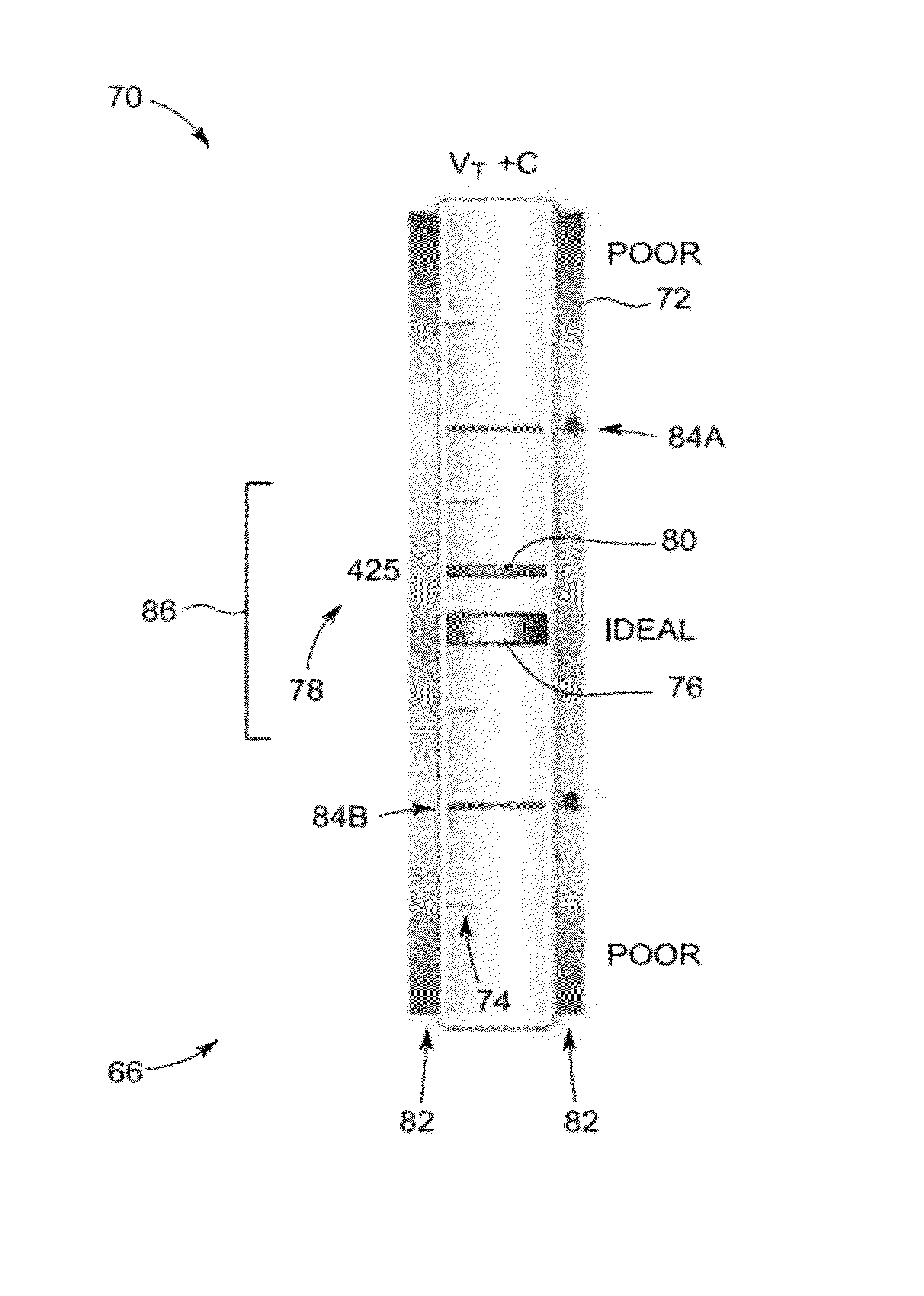
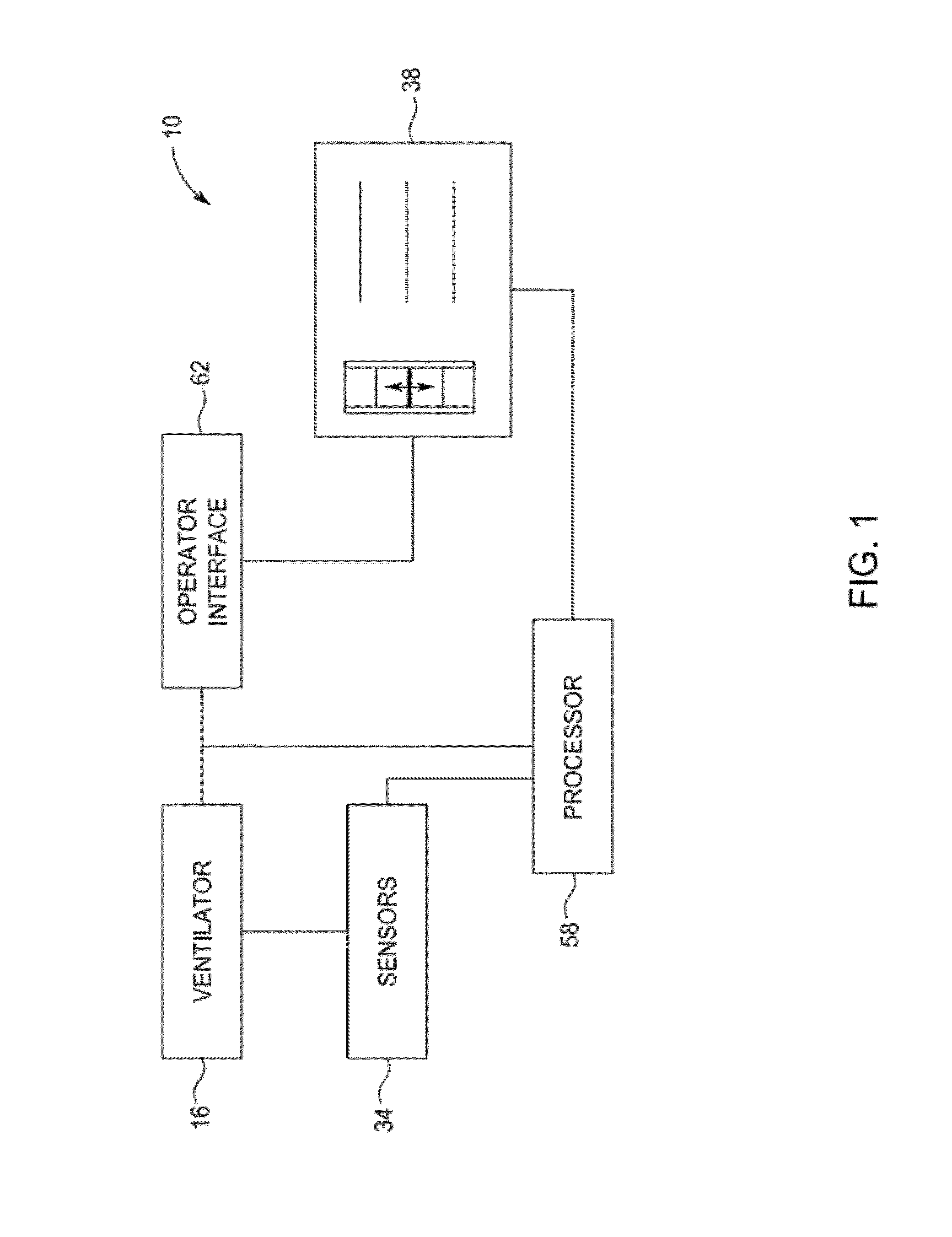
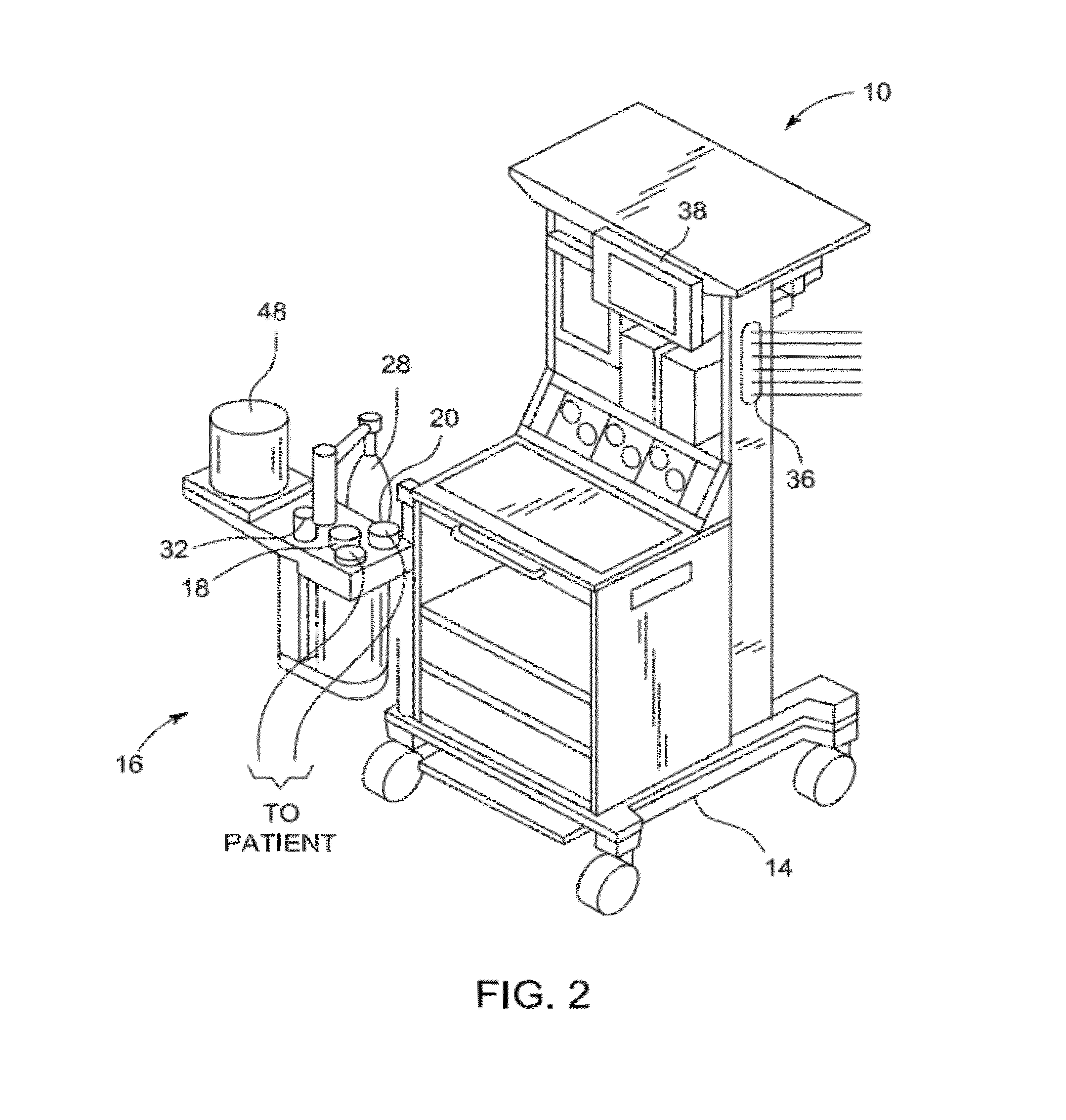
Methods and systems for visualizing mechanical ventilation information are provided. One system includes a user interface for a medical system having a ventilator is provided. The user interface includes a memory storing one or more sensor measurements for a patient and a processor. The processor is programmed to display a visualization of a tidal volume determined from one of the sensor measurements of the patient and display a visualization of lung compliance for the patient, wherein the tidal volume visualization and the lung compliance visualization are displayed concurrently.

Description

BACKGROUND OF THE INVENTION[0001]The subject matter disclosed herein relates generally to respiratory care systems, and more particularly, to mandatory mechanical ventilation systems.[0002]When patients are medically unable to breathe on their own, mechanical or forced ventilators can sustain life by providing requisite pulmonary gas exchanges for the patients. For example, conventional ventilators typically include electronic and pneumatic systems that control the pressure, flow rates, and / or volume of gases delivered to, and extracted from, patients needing medical respiratory assistance. Such control systems often include numerous user controls, such as knobs, dials, switches, and the like, for interfacing with treating clinicians, who support the patient's breathing by adjusting the pressure, flow rates, and / or volume of the patient's pulmonary gas exchanges, particularly as the condition and / or status of the patient changes. These parameter adjustments are challenging to contro...

Claims


Application Information

Patent Timeline
Patent Type & Authority Patents(United States)
IPC IPC(8): A61M16/00A61B5/091A61M16/01A61B5/00A61M16/10
CPCA61B5/742A61B5/091A61M16/0051A61M2205/502A61M2230/202A61M2230/205A61M2230/30A61M2230/432A61M2230/435A61M2230/437A61M2230/46A61M16/01A61M2016/0021A61M2016/0027A61M2016/0036A61M2016/103A61M2016/1025A61M2016/1035A61M16/024G16H20/40G16H40/63A61M16/0003A61M16/0057A61M2016/0015A61M2205/52
Inventor ROBINSON, SCOTT WILLIAMHUNSICKER, PAUL
Owner GENERAL ELECTRIC CO
Learn More