Die casting machine with l-shape frame

a technology of l-shape frame and die casting machine, which is applied in the field of die casting, can solve the problems of increasing production cost, increasing production cost, and causing upward arch deformation, and achieves the effects of reducing the influence of product deformation, improving product pass rate and production efficiency, and increasing the initial pressure variation valu

Active Publication Date: 2015-03-05
SUZHOU CHENGSHI CASTING
View PDF4 Cites 1 Cited by
  • Summary
  • Abstract
  • Description
  • Claims
  • Application Information

AI Technical Summary

Benefits of technology

[0046]5. The moving die device of the present invention also comprises a second deformation compensation device, said second deformation compensation device comprises, a first base plate, a second base plate arranged parallel with said first base plate; and said first base plate and said second base plate have a plurality of elastic components provided therebetween, said first base plate or said second base plate is in fixed connection with said moving die plate or said fixed die plate. In addition to the first deformation compensation device provided under the frame of the present invention, a second deformation compensation device is also provided on the moving die plate, and said moving die plate is provided close to the second deformation compensation device; in this way, thus, the second deformation compensation device may firstly compensate deformation of moving die plate and fixed die plate caused by injection pressure, and the deformation of the frame may be compensated by the first deformation compensation device. Therefore, it may help to significantly reduce the influence on the products due to deformation by using two deformation compensation devices to compensate the deformation in the process of die casting or injection molding, so as to significantly improve the percent of pass and production efficiency of products.
[0047]6. The screw bolt of the present invention is arranged extending through said first base plate and said second base plate, and said screw bolt is locked by a screw nut, in order to connect said disc springs between said first base plate and said second base plate in a pre-compressed manner. The elastic component between two base plates is in a pre-compressed state when it is mounted, the level of force of pre-compression is determined by the specific injection pressure, thereby increasing the initial pressure variation value when elastic component compensates the distortion, and the compression stroke that the moving die plate compress the elastic under injection pressure is decreased, and then the sealing effect when mold closing is enhanced.
[0048]7. The moving die device of the present invention also comprises a rapid pressurization and pressure relief device for pressurizing and relieving the pressure on said elastic components. On basis of the pre-compression of elastic component, said device may compress the elastic components again, which further improves the pressure resistance of the elastic components and resist the injection pressure, meanwhile said device may relieves the pressure after injecting the materials, and the elastic components is returned to the preliminary pre-compressed state, and this avoid the elastic components of being always in a high pressure state, in which

Problems solved by technology

During the process of injecting material or forming by compressing, distortion will be caused in moving die and fixed die, said distortion leads to a change of original shape of the die cavity, and eventually leads to a change of injection molding products or die casting products, even produces substandard products, seriously affect productivity, and increases production cost.
However, when the injection is larger, pressure on the moving die and the fixed die will be passed to a frame which supports the moving die and the fixed die, since the lower portion of the frame is fixed, the left and right ends of the frame are stretched outward by the above mentioned injection molding pressure, the moving die track, located on the upper side of the frame of injection molding machine, may have a upward arching deformation caused, and a deformation which squeezes from both ends toward the middle is caused in lateral board located on the lower side of the frame of injection molding machine.
This deformation increases the relative deformation between moving die and fixed die, thus seriously affects the shape of the injection molding products.
However, influences caused by deformation of the body of frame will always be ignored by technical staff, therefore only designing a deformation compensation devic

Method used


Image

  • Die casting machine with l-shape frame
  • Die casting machine with l-shape frame
  • Die casting machine with l-shape frame

Examples


embodiment 1

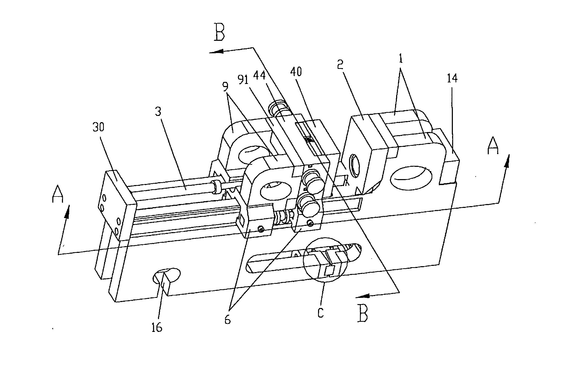
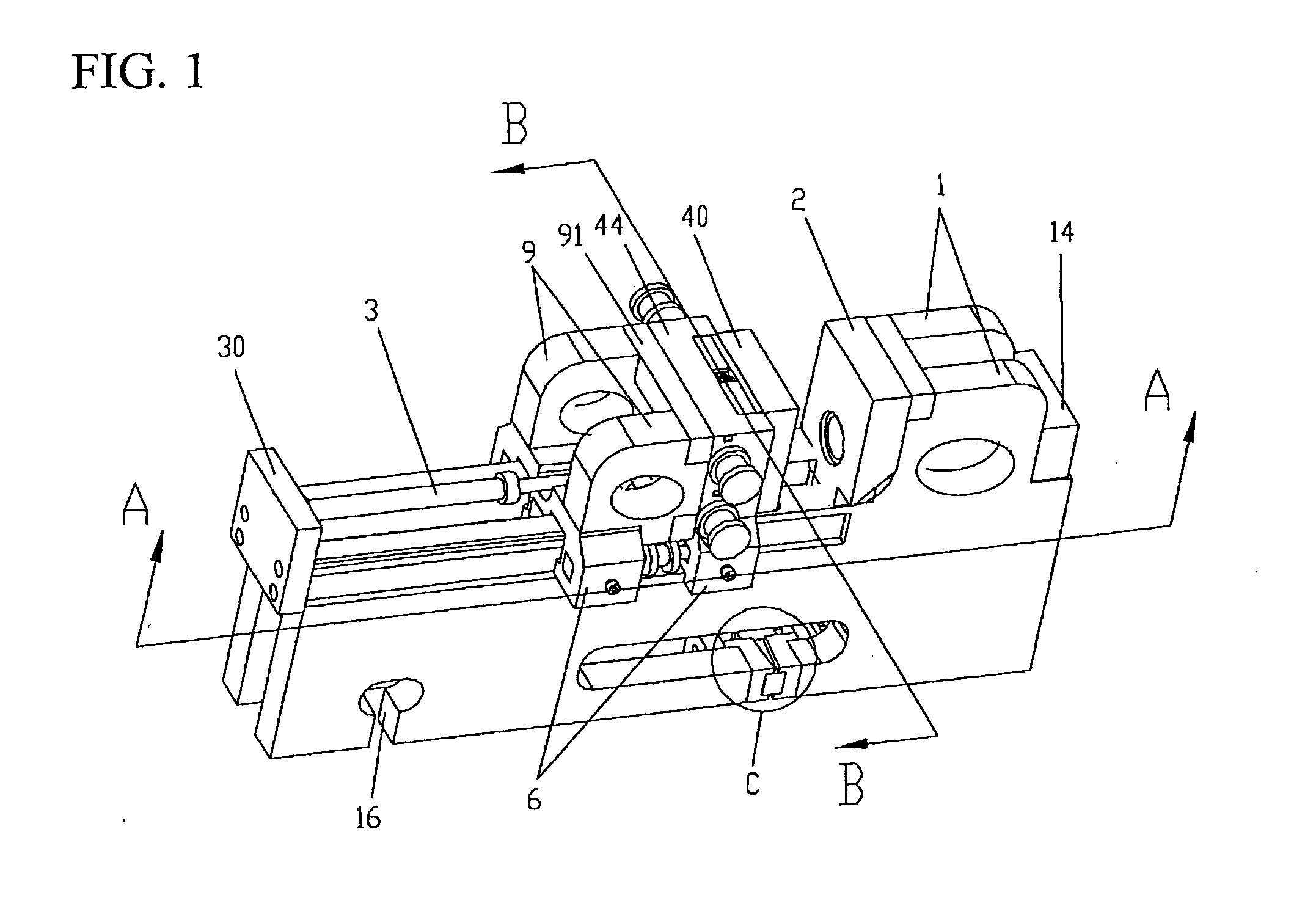
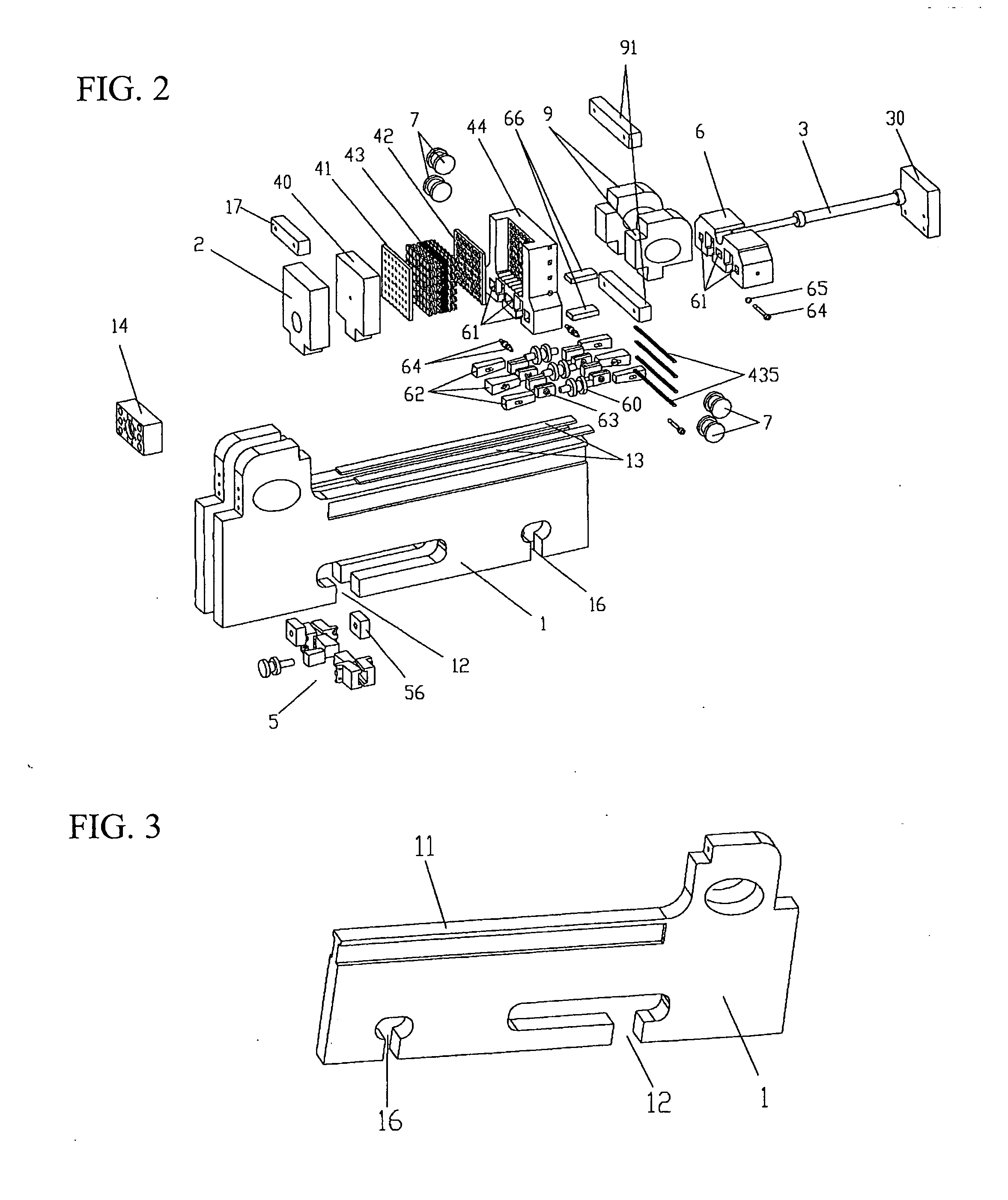
[0072]As shown in FIG. 1-2, the present invention disclose a die casting machine with L-shape frame, comprising two frames 1 arranged in parallel and with the same size and shape; a fixed die plate (2), fixed on one end of an upward extending side of said frame (1); a moving die device, disposed on the other side of said frame and slidable relative to said frame and comprising a moving die plate (40) opposite to said fixed die plate (2), and being lockable to said frame (1) by a mould clamping device (6); a notch (12), formed on a bottom of said frame (1); a first deformation compensation device (5), provided in said notch (12) and adapted for applying forces in opposite directions on both sides of said notch (12) while said moving die plate (40) is being clamped with said fixed die plate (2).

[0073]As a preferred structure of first deformation compensation device of the present invention, as shown in FIG. 3-5, in the present embodiment, said first deformation compensation device com...

embodiment 2

[0080]Base on the embodiment 1, as shown in FIG. 6-9, said die casting machine also comprises a second deformation compensation device, provided close to said moving die device and / or said fixed die plate (2), and said second deformation compensation device comprises a first base plate (41), a second base plate (42) arranged parallel with said first base plate (41); said first base plate (41) and said second base plate (42) have a plurality of elastic components (43) provided therebetween, said first base plate (41) or said second base plate (42) is in fixed connection with said moving die plate (40) or said fixed die plate (2). In the present embodiment, said first base plate is in fixed connection with said moving die plate 40.

[0081]In the present embodiment, several elastic components 43 are arranged regularly, specially, since said first base plate 41 and said second base plate 41 are regular rectangle plates, said elastic components 43 are arranged horizontally and vertically i...

embodiment 3

[0085]Base on the above mentioned embodiment 2, as shown in FIG. 9-10, said moving die device also comprises a rapid pressurization and pressure relief device for pressurizing and relieving the pressure on said elastic components (43). Said rapid pressurization and pressure relief device comprises a driving mechanism for driving the rotation of said screw bolt (431), an moving block (437) and a driving block (438), both of which are provided between said moving die plate (40) and an end part of said screw bolt (431) and connected with each other; said moving block (437) and said screw bolt (431) are circumferentially fixed with each other in a position-limited manner at the bolt head; said driving block (438) and said moving die plate (40) are circumferentially fixed with each other in a position-limited manner in the groove of said moving die plate 40. In the present embodiment, said driving block 438 is a rectangle block, said moving block 437 is a circularity block, and the side-...


PUM

PropertyMeasurementUnit
Forceaaaaaaaaaa
Pressureaaaaaaaaaa
Sizeaaaaaaaaaa

Abstract

The invention discloses die casting machine with L-shape frame, including at least one L-shape frame, fixed die plate, fixed on end of upward extending side of frame, moving die device, disposed on other side of frame and slidable relative to frame, including moving die plate opposite to fixed die plate, lockable to frame by mould clamping device; a notch, formed on bottom of frame, first deformation compensation device, provided in notch, adapted for applying forces in opposite directions on sides of notch, while moving die plate is clamped with fixed die plate. First deformation compensation device of the present invention is adapted to applying forces on sides of the notch in lower position of the frame, to compensate squeeze to central section on the bottom of frame, weakening elastic distortion of the track on the frame, and eliminates effects of die casting or injection molding products due to deformation.

Description

CROSS-REFERENCE TO RELATED APPLICATIONS[0001]Pursuant to 35 U.S.C. §119 and the Paris Convention Treaty, this application claims the benefit of Chinese Patent Application No. 201310386859.6 filed on Aug. 30, 2013, the contents of which are incorporated herein by reference.BACKGROUND OF THE INVENTION[0002]1. Field of the Invention[0003]The present invention relates to the technical field of die casting, particularly relates to a die casting machine with L-shape frame.[0004]2. Description of the Related Art[0005]When producing products by injection molding or die casting technology, the first thing is to assembly a moving die and a fixed die to form a die cavity of product, then inject molten material into the die cavity, and form the product under certain pressure. During the process of injecting material or forming by compressing, distortion will be caused in moving die and fixed die, said distortion leads to a change of original shape of the die cavity, and eventually leads to a ch...

Claims


Application Information

Patent Timeline
IPC IPC(8): B22D17/00B22D17/26B22D17/22
CPCB22D17/002B22D17/266B22D17/26B22D17/22B22D17/10
Inventor ZAMMATTIO, GIACOMO
Owner SUZHOU CHENGSHI CASTING
Why Eureka
Try Eureka