Anastomotic device

a technology of anastomosis and inserter, which is applied in the field of surgical fastener inserter instruments, can solve the problems of increased operation risk, inability to remove the cap with the thread, and inability to easily remove the cap, so as to simplify the delivery of inflation liquid, simple liquid supply, and uniform volume increase during inflating

Active Publication Date: 2015-03-05
TYCO HEALTHCARE GRP LP
View PDF16 Cites 9 Cited by
  • Summary
  • Abstract
  • Description
  • Claims
  • Application Information

AI Technical Summary

Benefits of technology

[0011]In order to avoid injuries to the intestinal tissue while inserting the anastomotic device, an isotonic saline solution or even water in the introducer sheath can rinse the intestine via the sphincter muscle. If the liquid is transported into the intestine passing the device on the side of the device, this is again retracted into the device while pushing then anastomotic device and is pressed out of the piece of the intestine.
[0024]The fluid supply channel can be led out of the actuating part and if required, connected to a liquid reservoir for inflation liquid. For example, the fluid supply channel can be configured as hose or with a hose, wherein the hose can jut out for example 3 to 4 cm from the actuating part. In a simple way, this facilitates connection of a filling syringe with the inflation liquid to the hose. The hose can have a screw-type cap at its open end, in particular a three-way connection, which allows the addition of different fluids on the one hand and / or the liquid-proof seal, on the other hand. The hose can be retracted laterally from the actuating part, which facilitates a connection to a reservoir. Further, the invention allows that a reservoir for inflation liquid is firmly connected with the actuating part and / or forms a part of the same. The anastomotic device has then a container or the like, which is filled with the inflation liquid. While inflating, the inflation liquid is withdrawn from the container via the fluid supply channel into the body lumen. Finally an equivalent embodiment can provide a fluid supply from outside via the introducer sheath and the head section, whereby the fluid can be supplied to the anastomotic device in an area, which lies between the head section and the actuating part of the said anastomotic device.

Problems solved by technology

Well-known anastomotic devices have the disadvantage that the surrounding body tissue often gets damaged during insertion into the body lumen and thus leads to pain after the operation.
The forward movement of the head section within the body lumen, in particular with heavily lined intestinal mucosa, is then clearly affected and the operational risk increased.
Therefore, the cap covers at least those front areas of the head section, which are relatively sharp edged and can lead to injuries while inserting the head section through the anal canal.
In the case of known clamp inserter, it is disadvantageous that the cap is taken off via a thread from the head section and afterwards remains by the side of the head section.
When taking out the thread and by arranging the cap beside the head section it can cause injuries to the surrounding tissue in case of movement of the head section.
In all other respects, it can be seen that taking off the cap with the thread is not easily possible, if the head section on the side of the thread lies close against the tissue.
Even pulling the cap out of a body lumen with the help of the thread is difficult and can lead to further injuries of the body tissue.
By collapsing the lumen it can happen that the body tissue from outside lies close to an outside peripheral area of the head section and thus a liquid delivery across the periphery and / or side of the head section is rendered more difficult.

Method used


Image

  • Anastomotic device
  • Anastomotic device
  • Anastomotic device

Examples


Embodiment Construction

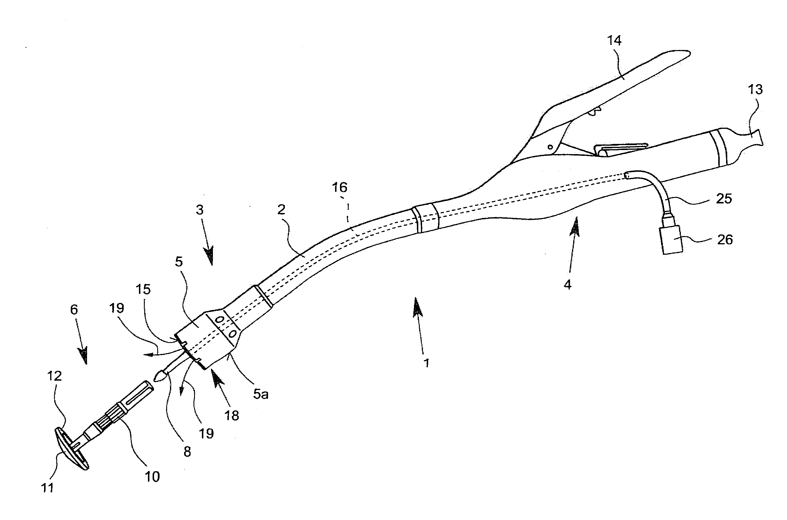
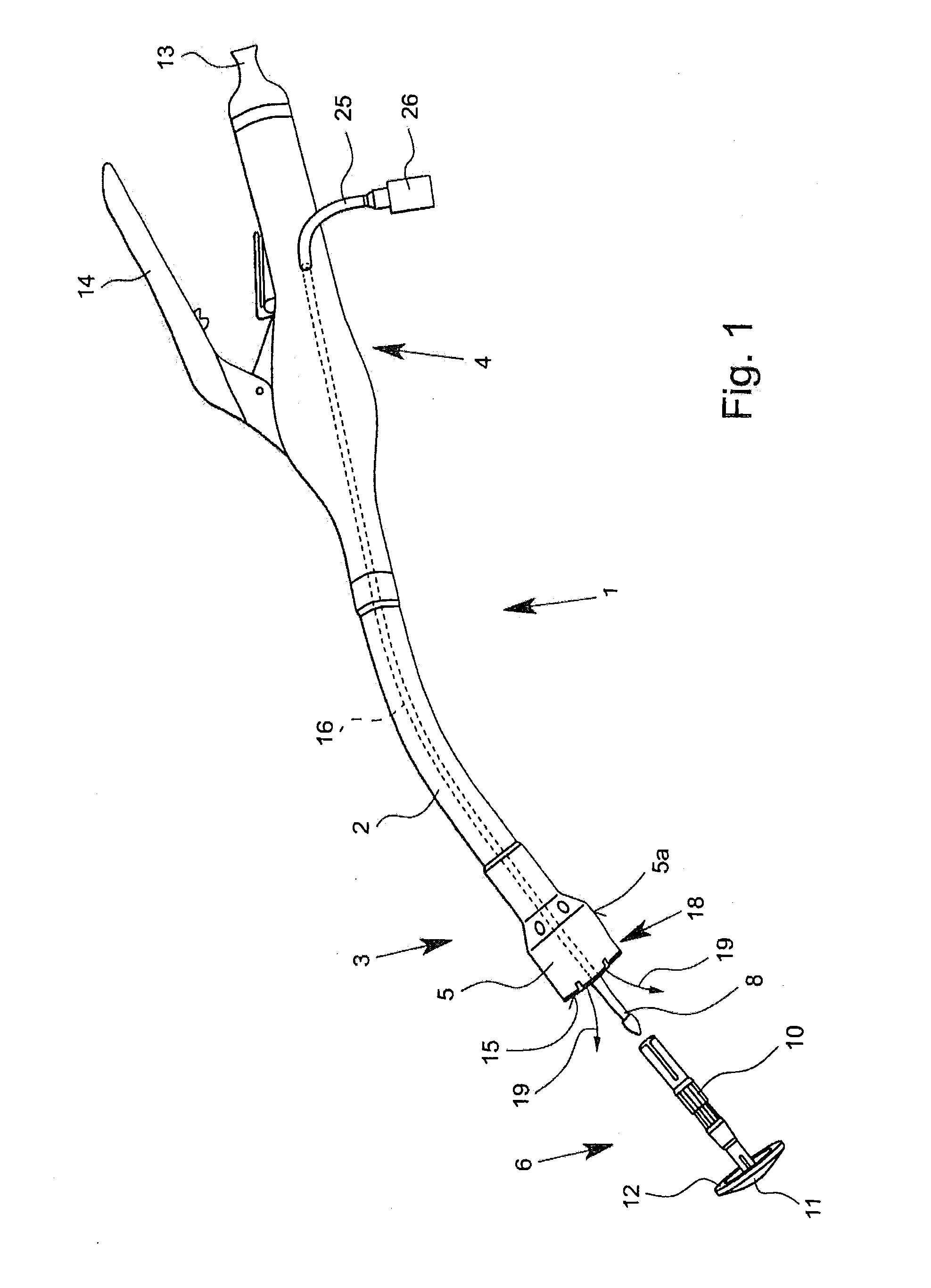
[0032]The disclosure relates to anastomotic device for the formation of anastomoses, in particular intestinal anastomoses, with an introducer sheath for feeding into a body lumen, preferably into the large intestine, with a particularly thickened or swelled head section at the distal end of the introducer sheath and with an actuating part at the proximal end of the introducer sheath. The anastomotic device has an anvil section with a thrust bearing part, and a retractable and extendable knife and a retaining pin arranged within the head section. The thrust bearing part can be moved relative to the head section. The retaining pin can be joined to the thrust bearing part of the anvil section. The thrust bearing part can be moved by moving the retaining pin into the head section. From the viewpoint of invention, the expressions “proximal” and “distal” refer to the field of vision of the person operating the anastomotic device, i.e. “proximal” on the person with respect to the side turn...


PUM

PropertyMeasurementUnit
widthaaaaaaaaaa
widthaaaaaaaaaa
areaaaaaaaaaaa

Abstract

Illustrated and described is an anastomotic device for forming anastomoses, in particular of intestine anastomoses, with an introducer sheath for insertion into a body lumen, wherein a thrust bearing part is provided for the head section and within the head section an extendable and retractable knife and a retaining pin are arranged. According to the invention at least the actuating part and the head section of inter-connected fluid supply channel and at the head section at least one fluid outlet connected with the fluid supply channel are provided for producing a fluidic connection between the actuating part and the head section while inserting the head section into the body lumen and / or when pushing the introducer sheath into the body lumen, in which the fluidic connection is configured for discharging an inflation liquid into the body lumen.

Description

CROSS-REFERENCE TO RELATED APPLICATIONS[0001]This application is a national filing of international application no. PCT / EP2011 / 003609, which claims the benefit of German Patent Application Serial no. 10 2011 102 686.3, filed May 20, 2011, the disclosure of which is hereby incorporated by reference herein.BACKGROUND[0002]1. Technical Field[0003]The present disclosure relates to surgical fastener inserter instruments, and more particularly to surgical fastener inserter instruments for joining tubular sections of tissue such as intestinal anastomoses.[0004]2. Background of Related Art[0005]The present disclosure relates to anastomotic devices for the formation of anastomoses and, in particular, to intestinal anastomoses. In surgery, operationally produced connections between blood vessels, nerves and hollow organs, like, for example, sections of the large intestines, are designated as an anastomoses. Fundamentally, the anastomosis is understood as a connection between two anatomical st...

Claims


Application Information

Patent Timeline
Patent Type & Authority Applications(United States)
IPC IPC(8): A61B17/115A61B17/11
CPCA61B17/115A61B17/1155A61B2017/07285A61B2019/481A61B2017/07257A61B17/1114A61B2217/007A61B2090/08021
Inventor VESTWEBER, BORIS
Owner TYCO HEALTHCARE GRP LP
Why Eureka
Try Eureka