Photocoupler

a photocoupler and photoelectric technology, applied in the field of photocouplers, can solve the problems of large capacitance value, low cmrr (common mode rejection ratio), inability to meet the required standard, etc., and achieve the effect of reducing capacitance value, increasing cmrr, and minimizing overlap area

Active Publication Date: 2015-03-05
CHEW POH LOONG
View PDF8 Cites 2 Cited by
  • Summary
  • Abstract
  • Description
  • Claims
  • Application Information

AI Technical Summary

Benefits of technology

[0014]The present invention applies the optically reflective surface to reflect the light from the light emitting element to the light-sensing element, minimizes the overlapping area between the two...

Problems solved by technology

However, the electrical characteristics of the conventional photocoupler is unable to meet the required standard when the electrical characteristics of the photocoupler is affected due to a distance bei...

Method used


Image

  • Photocoupler
  • Photocoupler

Examples


Embodiment Construction

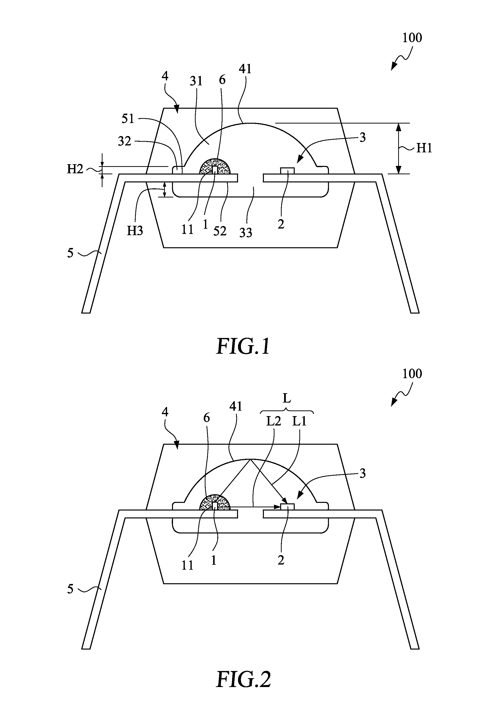
[0018]The embodiment is described in detail below with reference to the FIG. 1 and FIG. 2, and the description is only for explaining the embodiment of the present invention, but not for limiting the scope of the present invention.

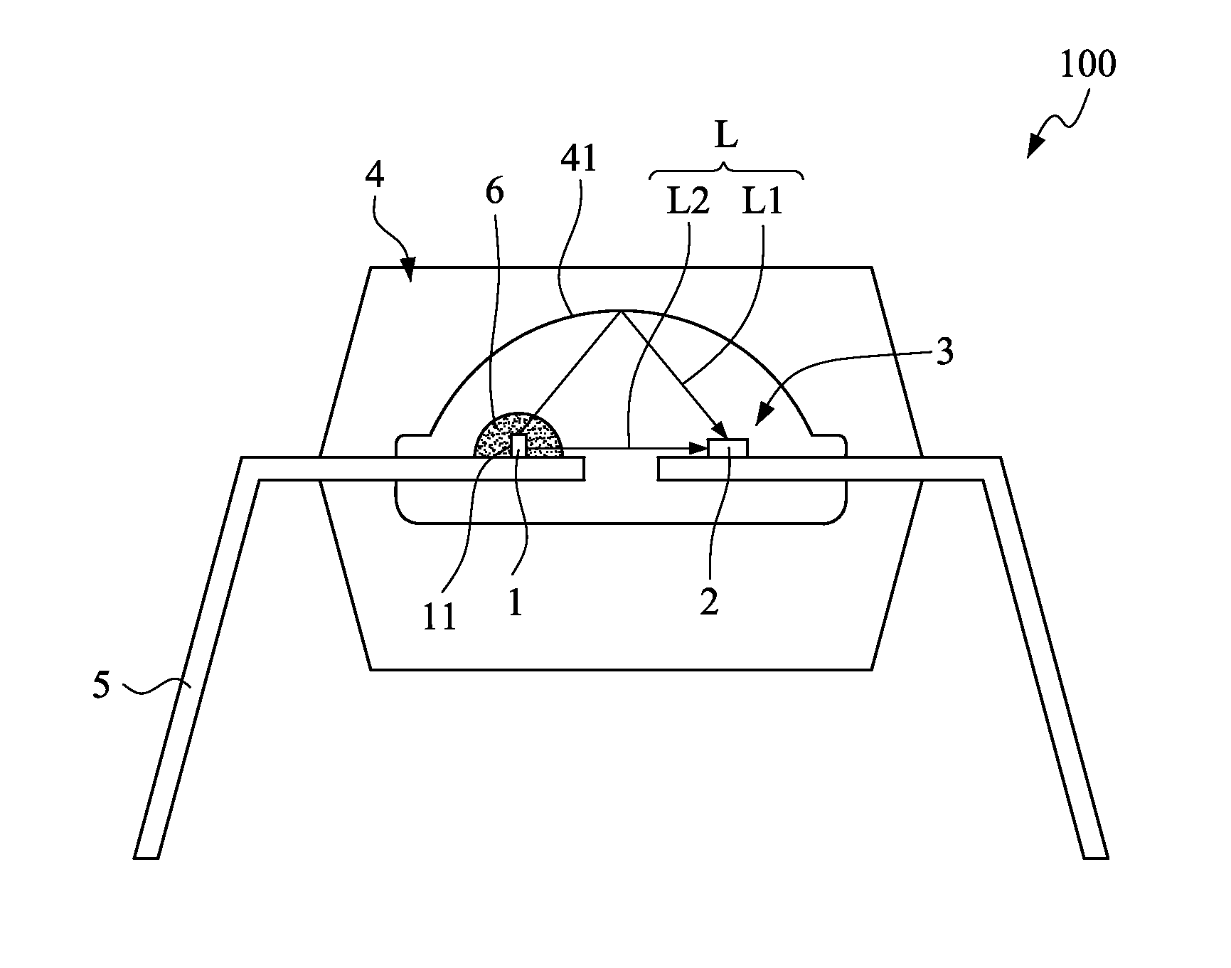
[0019]As illustrated in FIG. 1, a photocoupler 100 of an embodiment according to the present invention includes a light emitting element 1, a light-sensing element 2, a transparent inner encapsulant body 3, an outer covering body 4, and two conductive frames 5.

[0020]The light emitting element 1 is used for emitting a light L and is provided on the conductive frame 5. The light emitting element 1, for example, is an infrared light emitting diode. It will be further appreciated that the light emitting element 1 can be replaced with other light emitting component, e.g. a visible light emitting diode, a laser light-emitting diode, or a plasma light emitting diode. The light-sensing element 2 is used for receiving the light L and is provided on the another cond...


PUM


Abstract

A photocoupler comprises a light emitting element, a light-sensing element, a transparent inner encapsulant body, an outer covering body, and two conductive frames on which. An optically reflective surface is in contact and formed between the dome enclosing portion of the transparent inner encapsulant body and the outer encapsulant body. A portion of the light emitted by the light emitting element is reflected to the light-sensing element through the optically reflective surface, and the other portion of the light emitted from the light emitting element is directly emitting to the light-sensing element through the transparent inner encapsulant body. The present invention applies the optically reflective surface to minimize the overlapping area between the two conductive frames, and reduces the capacitance value, and increases the CMRR in a manner that the photo coupler of the present invention is able to meet the standard of electrical characteristics as required.

Description

FIELD OF THE INVENTION[0001]The present invention relates to an electronic component, and more particularly to a photocoupler.BACKGROUND OF THE INVENTION[0002]Photocoupler is a component that transfers electrical signals in form of light between two isolated circuits. A conventional photocoupler generally includes two conductive frames, a light-sensing element provided on an upper surface of one conductive frame, and a light emitting element provided on a lower surface of the other conductive frame. The light emitting element is driven by an input electric signal to convert the input electric signal to a light signal, and the light-sensing element is for receiving the light signal and then outputting an electric signal converted from the light signal.[0003]The photocoupler has been widely used in various electrical products. However, the electrical characteristics of the conventional photocoupler is unable to meet the required standard when the electrical characteristics of the phot...

Claims


Application Information

Patent Timeline
IPC IPC(8): H01L31/16
CPCH01L31/16H01L31/02325H01L2924/181H01L31/173H01L2924/00012
Inventor CHEW, POH-LOONG
Owner CHEW POH LOONG
Why Eureka
Try Eureka