Support supply apparatus and method for supplying support

a technology of support and apparatus, applied in the direction of feeding apparatus, conveyor parts, solid-state devices, etc., can solve the problem of accidental application of force, and achieve the effect of cleaning the surfa

Active Publication Date: 2015-03-05
SEMICON ENERGY LAB CO LTD
View PDF45 Cites 47 Cited by
  • Summary
  • Abstract
  • Description
  • Claims
  • Application Information

AI Technical Summary

Benefits of technology

[0022]According to one embodiment of the present invention, an apparatus for supplying a support having a clean surface can be provide

Problems solved by technology

For example, portable information processors are often used outdoors, and force might be accid

Method used


Image

  • Support supply apparatus and method for supplying support
  • Support supply apparatus and method for supplying support
  • Support supply apparatus and method for supplying support

Examples


embodiment 1

[0067]In this embodiment, a structure of a support supply apparatus of one embodiment of the present invention is described with reference to FIG. 1, FIGS. 2A1, 2A2, 2B1, 2B2, 2C1, and 2C2, FIGS. 3A to 3D, FIGS. 4A1, 4A2, 4B1, 4B2, 4C1, 4C2, 4D1, and 4D2, and FIGS. 5A and 5B.

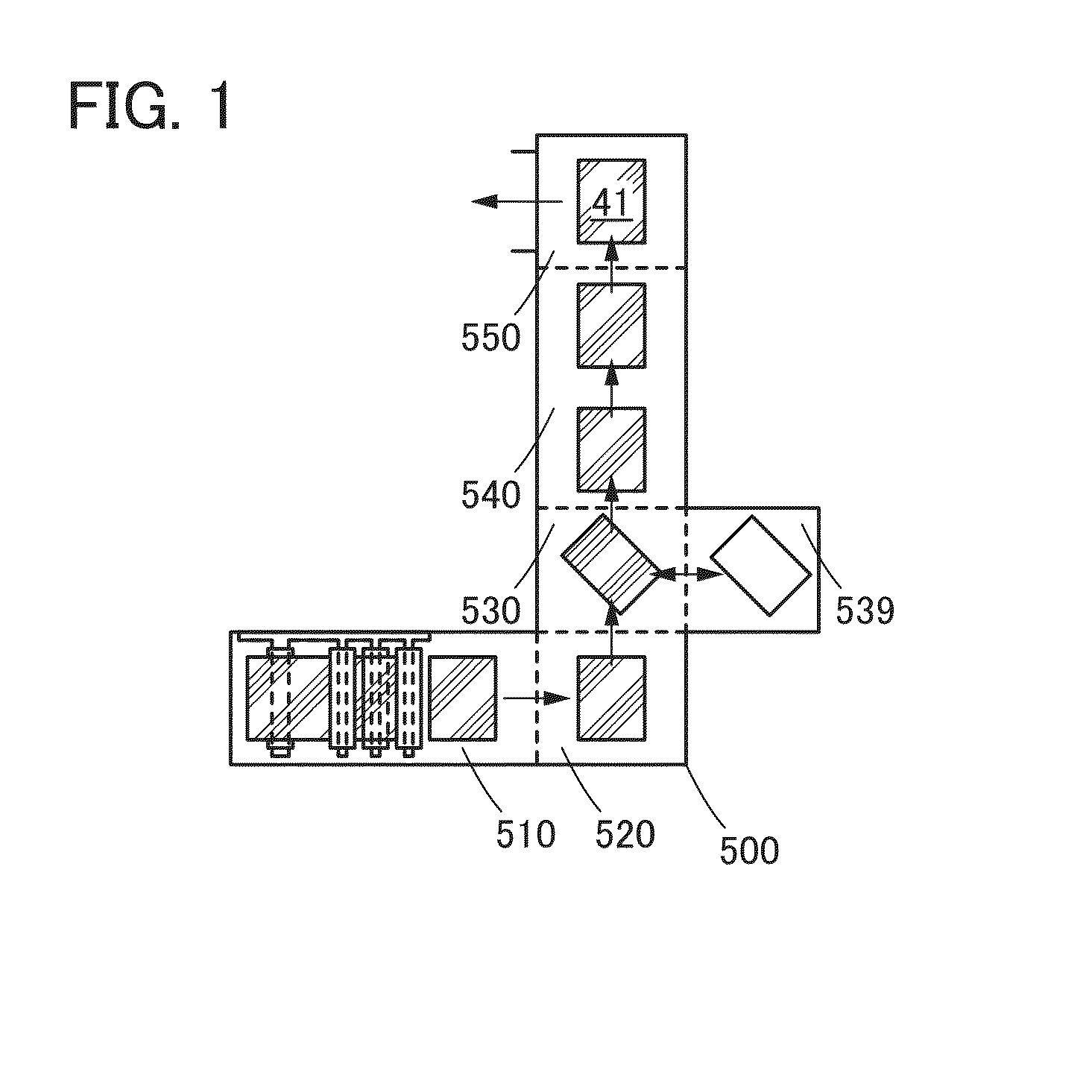
[0068]FIG. 1 is a schematic view illustrating a structure of a support supply apparatus 500 of one embodiment of the present invention.

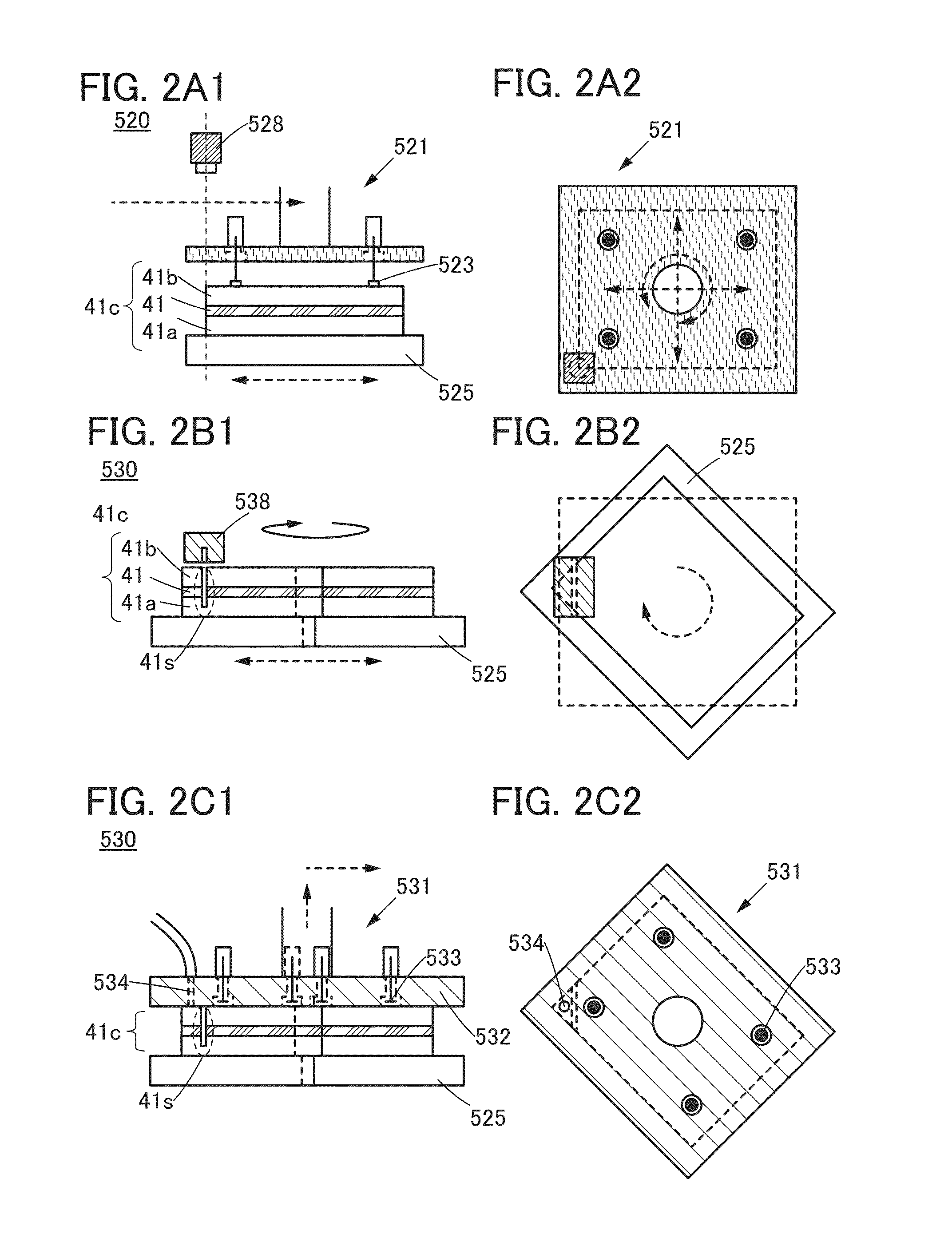
[0069]FIGS. 2A1, 2A2, 2B1, 2B2, 2C1, and 2C2 illustrate structures and operations of a positioning portion 520 and a slit formation portion 530 of the support supply apparatus 500 of one embodiment of the present invention.

[0070]FIGS. 3A to 3D illustrate an operation of a peeling portion 539 of the support supply apparatus 500 of one embodiment of the present invention.

[0071]FIGS. 4A1, 4A2, 4B1, 4B2, 4C1, 4C2, 4D1, and 4D2 illustrate a structure and operation of a pretreatment portion 540 of the support supply apparatus 500 of one embodiment of the present invention.

[0072]FIGS. 5...

embodiment 2

[0141]In this embodiment, a structure of a stack manufacturing apparatus of one embodiment of the present invention is described with reference to FIG. 6 and FIGS. 7A1, 7A2, 7B1, 7B2, 7C, 7D1, 7D2, 7E1, and 7E2.

[0142]FIG. 6 is a schematic view illustrating a structure of a stack manufacturing apparatus 1000A that is one embodiment of the present invention, and a conveyance path of a processed member and a stack in a process. FIGS. 7A1, 7A2, 7B1, 7B2, 7C, 7D1, 7D2, 7E1, and 7E2 are schematic views illustrating a process for manufacturing a stack with the use of the stack manufacturing apparatus 1000A that is one embodiment of the present invention. FIGS. 7A1, 7B1, 7D1, and 7E1 on the left side are cross-sectional views (along line X1-X2) illustrating structures of a processed member and a stack. FIGS. 7A2, 7B2, 7D2, and 7E2 on the right side are top views corresponding to the cross-sectional views.

1000A>

[0143]The stack manufacturing apparatus 1000A described in this embodiment includ...

embodiment 3

[0176]In this embodiment, a structure of a stack manufacturing apparatus of one embodiment of the present invention is described with reference to FIG. 8, FIGS. 9A1, 9A2, 9B1, 9B2, 9C, 9D1, 9D2, 9E1, and 9E2, and FIGS. 10A1, 10A2, 10B, 10C, 10D1, 10D2, 10E1, and 10E2.

[0177]FIG. 8 is a schematic view illustrating a structure of a stack manufacturing apparatus 1000 that is one embodiment of the present invention, and the conveyance path of a processed member and a stack in a process.

[0178]FIGS. 9A1, 9A2, 9B1, 9B2, 9C, 9D1, 9D2, 9E1, and 9E2 and FIGS. 10A1, 10A2, 10B, 10C, 10D1, 10D2, 10E1, and 10E2 are schematic views illustrating a process for manufacturing a stack with the use of the stack manufacturing apparatus 1000 that is one embodiment of the present invention. FIGS. 9A1, 9B1, 9D1, and 9E1 and FIGS. 10A1, 10D1, and 10E1 on the left side are cross-sectional views (along line Y1-Y2 or Y3-Y4) illustrating structures of a processed member and a stack. FIGS. 9A2, 9B2, 9D2, and 9E2 a...


PUM

PropertyMeasurementUnit
Sizeaaaaaaaaaa

Abstract

An apparatus for supplying a support having a clean surface is provided. Alternatively, an apparatus for manufacturing a stack including a support and a remaining portion of a processed member whose one surface layer is separated is provided. A positioning portion, a slit formation portion, and a peeling portion are included. The positioning portion is provided with a first transfer mechanism of a stacked film including a support and a separator and a table for fixing the stacked film. The slit formation portion is provided with a cutter that can form a slit which does not pass through the separator. The peeling portion is provided with a second transfer mechanism and a peeling mechanism extending the separator and then peeling the separator. In addition, a pretreatment portion activating a support surface is included.

Description

BACKGROUND OF THE INVENTION[0001]1. Field of the Invention[0002]The present invention relates to an object, a method, or a manufacturing method. In addition, the present invention relates to a process, a machine, manufacture, or a composition of matter. Specifically, the present invention relates to, for example, a semiconductor device, a display device, a light-emitting device, a power storage device, a driving method thereof, or a manufacturing method thereof. More specifically, one embodiment of the present invention relates to a support supply apparatus or a stack manufacturing apparatus.[0003]2. Description of the Related Art[0004]The social infrastructures relating to means for transmitting information have advanced. This has made it possible to acquire, process, and send out many pieces and various kinds of information with the use of an information processor not only at home or office but also at other visiting places.[0005]With this being the situation, portable information...

Claims


Application Information

Patent Timeline
IPC IPC(8): H01L51/52H01L51/56H01L27/32B08B5/02B08B5/04
CPCH01L51/5237B08B5/023H01L2227/323H01L27/3244H01L51/56B08B5/04B65G49/069B65G2249/04B32B17/06Y10T29/53091Y10T29/5317Y10T156/1121Y10T156/1939Y10T156/1184Y10T156/1917Y10T156/1137Y10T156/1922Y10T156/1158Y10T156/1967B65G49/068H10K59/1201H10K71/00H01L21/67715H01L21/6773B32B38/10H01L2221/68318H01L21/68H01L21/673H01L21/67333H10K50/84H10K59/12B32B37/025B32B43/006B32B2457/00B32B2457/14B32B2457/20B65H3/0816B65H3/48B65H16/00B65H35/0006
Inventor OHNO, MASAKATSUYOKOYAMA, KOHEIIDOJIRI, SATORUIKEDA, HISAOJINBO, YASUHIROADACHI, HIROKIHIRAKATA, YOSHIHARUEGUCHI, SHINGO
Owner SEMICON ENERGY LAB CO LTD
Why Eureka
Try Eureka