Method and device for transmitting heat between waste water located in a tank and a fluid

a technology of waste water and heat exchanger, which is applied in the direction of multi-stage water/sewage treatment, flush cleaning, separation process, etc., can solve the problem of high cost of heat exchange, and achieve the effect of improving the thermal transfer through the heat exchanger

Active Publication Date: 2010-03-18
HUBER SE
View PDF7 Cites 19 Cited by
  • Summary
  • Abstract
  • Description
  • Claims
  • Application Information

AI Technical Summary

Benefits of technology

[0015]According to the invention, wastewater flows through a container in which a heat exchanger is located during which a convective flow is produced that on the one hand serves as an aid for cleaning the wastewater and at the same time is also utilized for cleaning the outer surface of the heat exchanger as well as for improving the thermal transfer through the heat exchanger.

Problems solved by technology

Since the convective flows serve to clean the wastewater as well as to recover heat, the expense for this occurs only once.

Method used


Image

  • Method and device for transmitting heat between waste water located in a tank and a fluid
  • Method and device for transmitting heat between waste water located in a tank and a fluid
  • Method and device for transmitting heat between waste water located in a tank and a fluid

Examples


Embodiment Construction

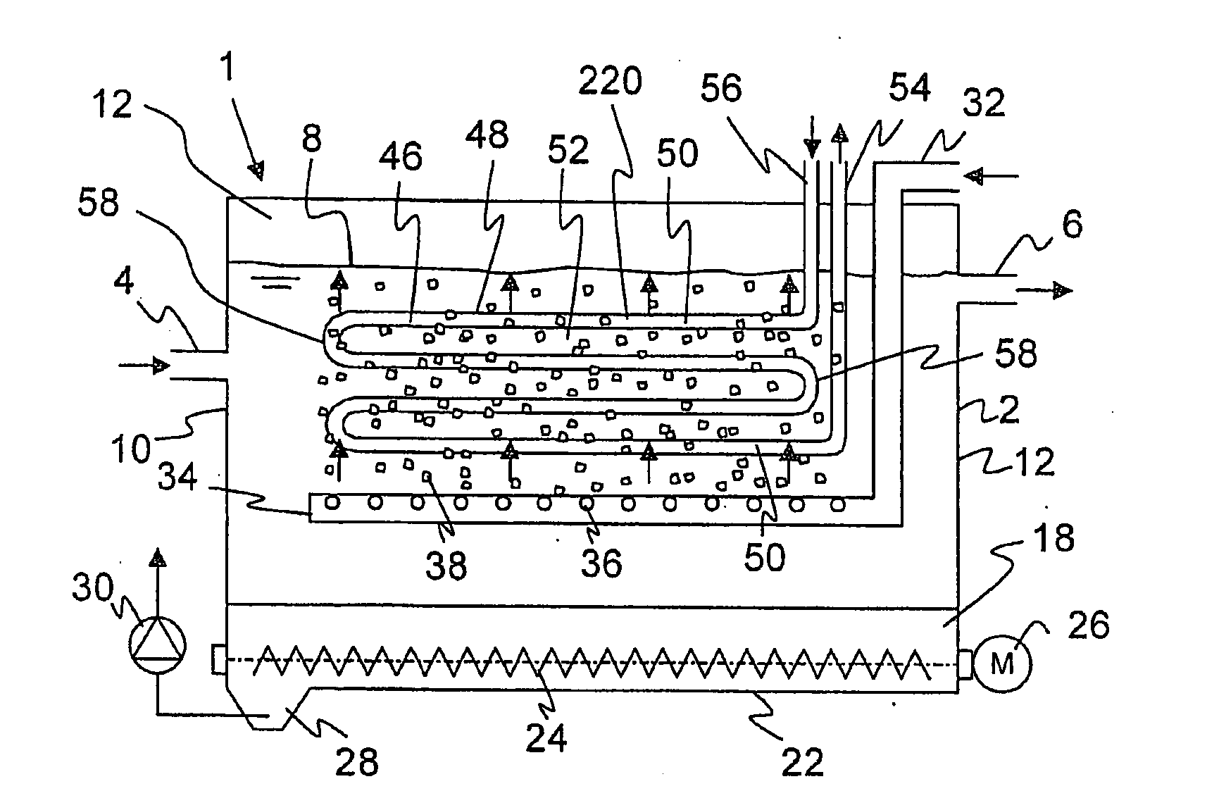
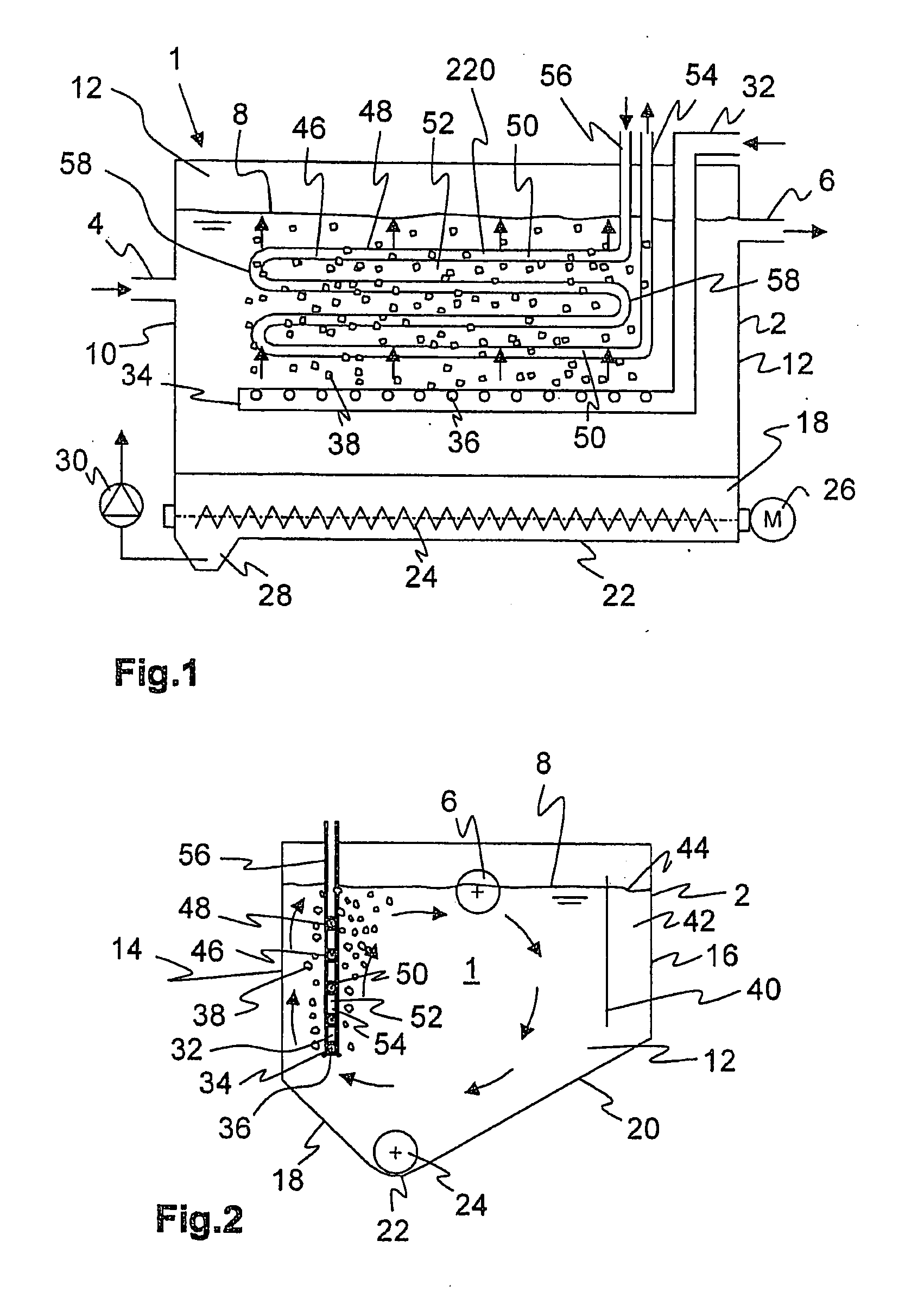
[0052]FIGS. 1, 2 show a sand trap 1 with a rectangular base area, Sand trap 1 consists of a basin 2 with an inlet 4 and an outlet 6 for wastewater flowing through sand trap 1. Basin 2 can be manufactured from concrete, metal or plastic. Basin 2 is filled with wastewater up to a certain water level 8. Basin 2 has vertical front walls 10, 12 and side walls 14, 16 as well as oblique bottom areas 18, 20 inclined to a drain 22 so that sand settling in sand trap 1 slides into drain 22. A worm conveyor 24 is arranged in drain 22, is driven by a motor 26 and pushes the separated sand to a sump 28. The sand is discharged from sump 28 by a pump 30 and usually delivered to a sand classifier or sand washer (not shown). Pump 30 can be a rotary pump or also an air-lift pump (a compressed-air lift pump).

[0053]Represented sand trap 1, a long sand trap in this exemplary embodiment, is aerated. Air is supplied from a blower (not shown) via a pressure line 32 to a diffusion pipe 34 arranged horizontal...


PUM

PropertyMeasurementUnit
heataaaaaaaaaa
cross-sectional areaaaaaaaaaaa
temperatureaaaaaaaaaa

Abstract

A method for transferring heat includes flowing a wastewater through a tank and flowing a fluid through a heat exchanger having an outer surface. The method further includes aerating the wastewater to produce a convective flow, contacting the outer surface of the heat exchanger with the convective flow to exchange heat, and cleaning the outer surface of the heat exchanger with the convective flow. A system for transferring heat includes a tank, a heat exchanger with an outer surface disposed in the tank, and a fluid flowing through the heat exchanger. Wastewater located in the tank flows over the outer surface of the heat exchanger, and a diffusion pipe disposed in the tank provides air into the tank to produce a convective flow in the wastewater.

Description

FIELD OF THE INVENTION[0001]The present invention relates to a process for transferring heat between wastewater located in a container and a fluid by means of a heat exchanger through which the fluid flows. The heat exchanger has an outer surface contacted by the wastewater, and a convective flow is produced in the wastewater that moves the wastewater along the outer surface and to an apparatus for carrying out the process.BACKGROUND OF THE INVENTION[0002]The wastewater can be domestic, municipal, trade or industrial wastewater. The fluid can be, for example, water, an aqueous solution, alcohol or oil. Heat is transferred from the wastewater to the fluid to either cool the wastewater or heat the fluid. In particular, the heated fluid can be conducted in a circuit by a heat pump in order to render the wastewater heat utilizable for heating purposes. Inversely, however, heat can also be transferred from the fluid to the wastewater in order to heat the latter and thus make it easier to...

Claims


Application Information

Patent Timeline
Patent Type & Authority Applications(United States)
IPC IPC(8): F28G13/00F28F13/12F28F1/00
CPCF28D1/0213F28D1/06F28D21/0012Y02B30/566F28G1/02F28G9/00F28F13/06Y02B30/56Y02A20/30
Inventor FROMMANN, CHRISTIAN
Owner HUBER SE
Why Eureka
Try Eureka