coil

a coil winding and coil technology, applied in the field of coils, can solve the problems of increasing the time required the cost of the facility for the coil winding process, and achieve the effect of suppressing the production of vibration and nois

Active Publication Date: 2015-03-05
AISIN AW CO LTD
View PDF7 Cites 9 Cited by
  • Summary
  • Abstract
  • Description
  • Claims
  • Application Information

AI Technical Summary

Benefits of technology

[0014]According to this configuration, a harmonic component included in a rotating magnetic field formed by the coil can be reduced. This can suppress production of vibration and noise during operation of the rotating electrical machine in the case where the coil is a coil for rotating electrical machines.

Problems solved by technology

The configuration of Patent Document 1 therefore complicates a coil winding process of winding the coil around a core, and may increase time required for the coil winding process and cost of facilities for the coil winding process.

Method used


Image

  • coil
  • coil
  • coil

Examples


first embodiment

1. First Embodiment

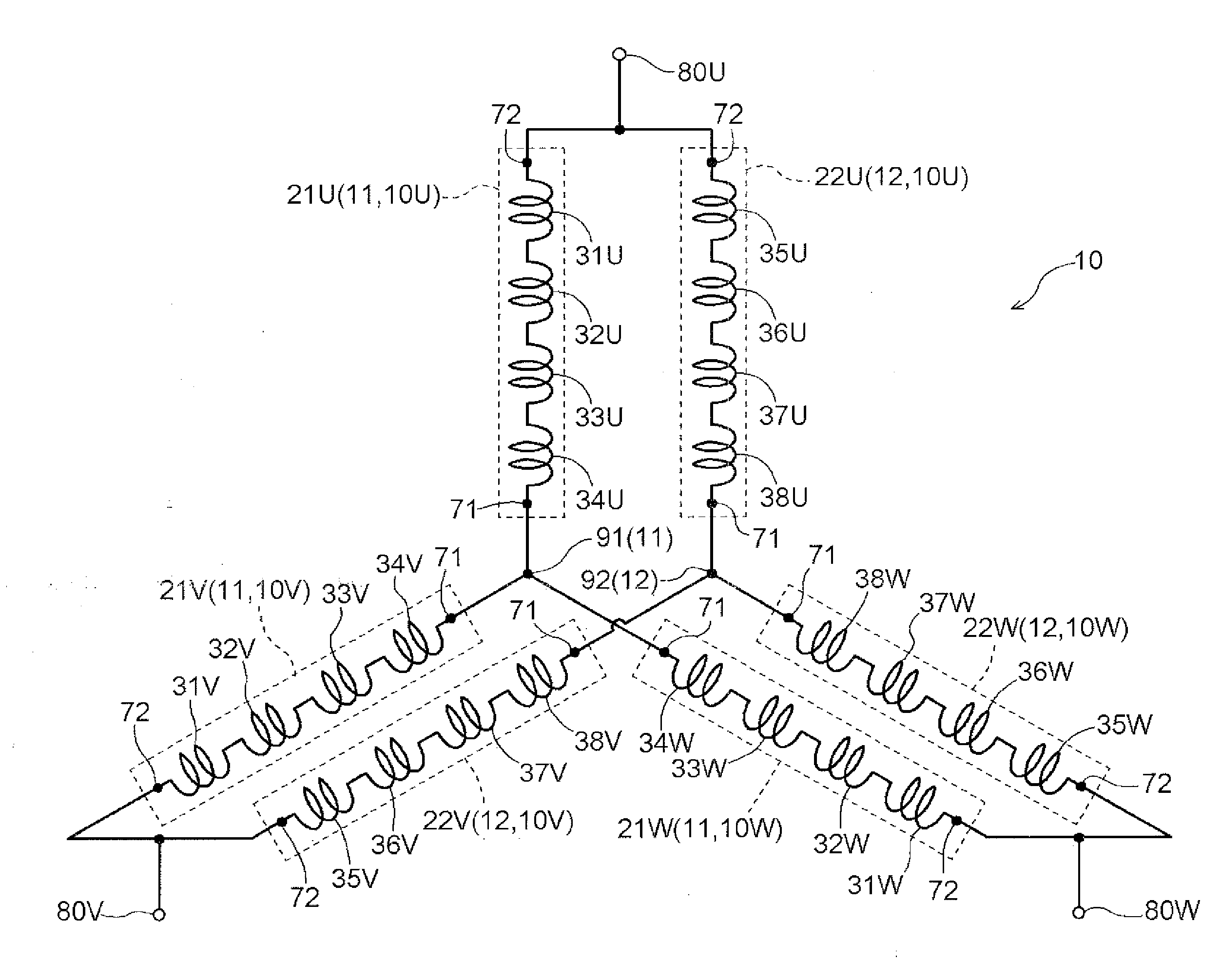
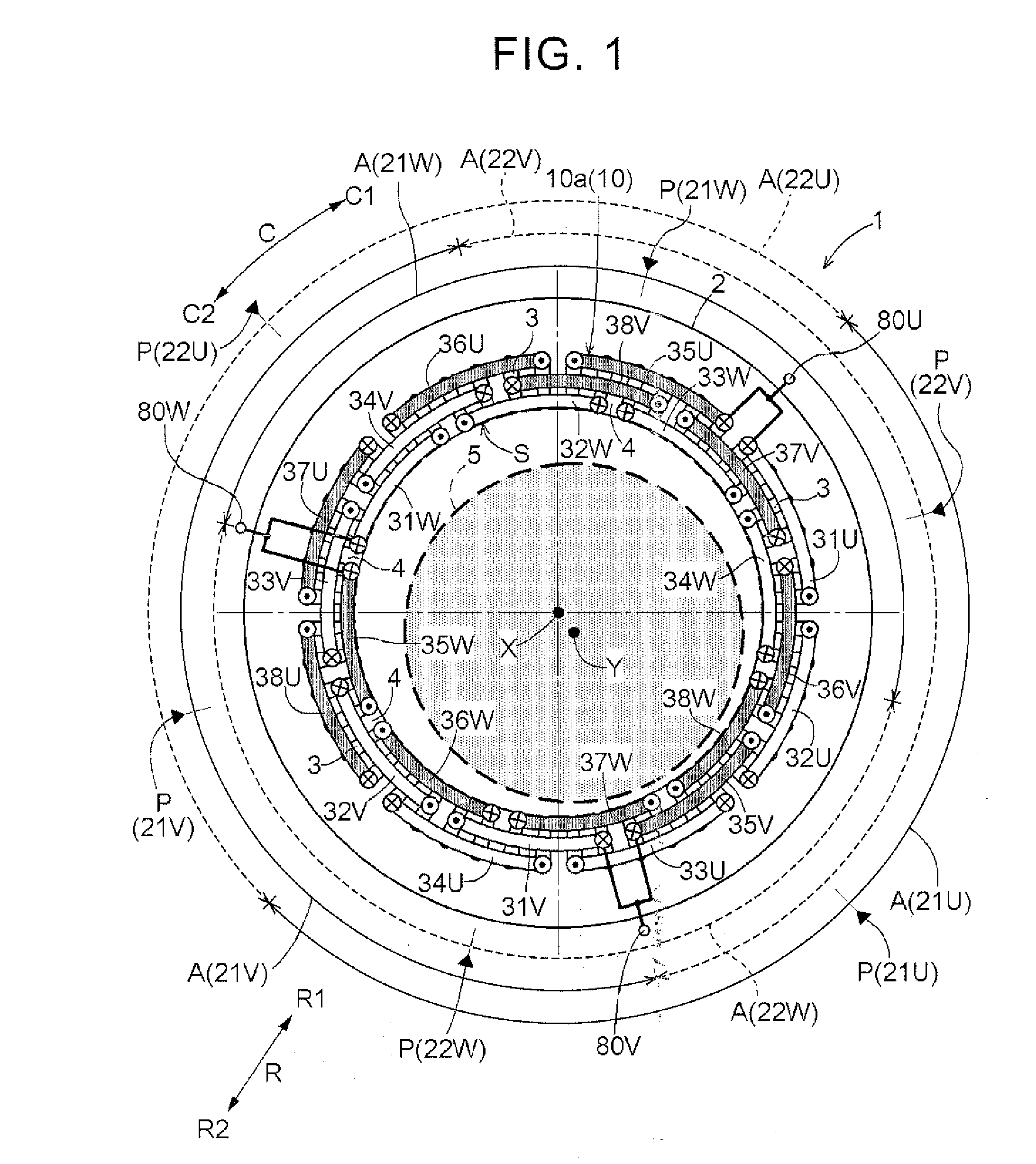
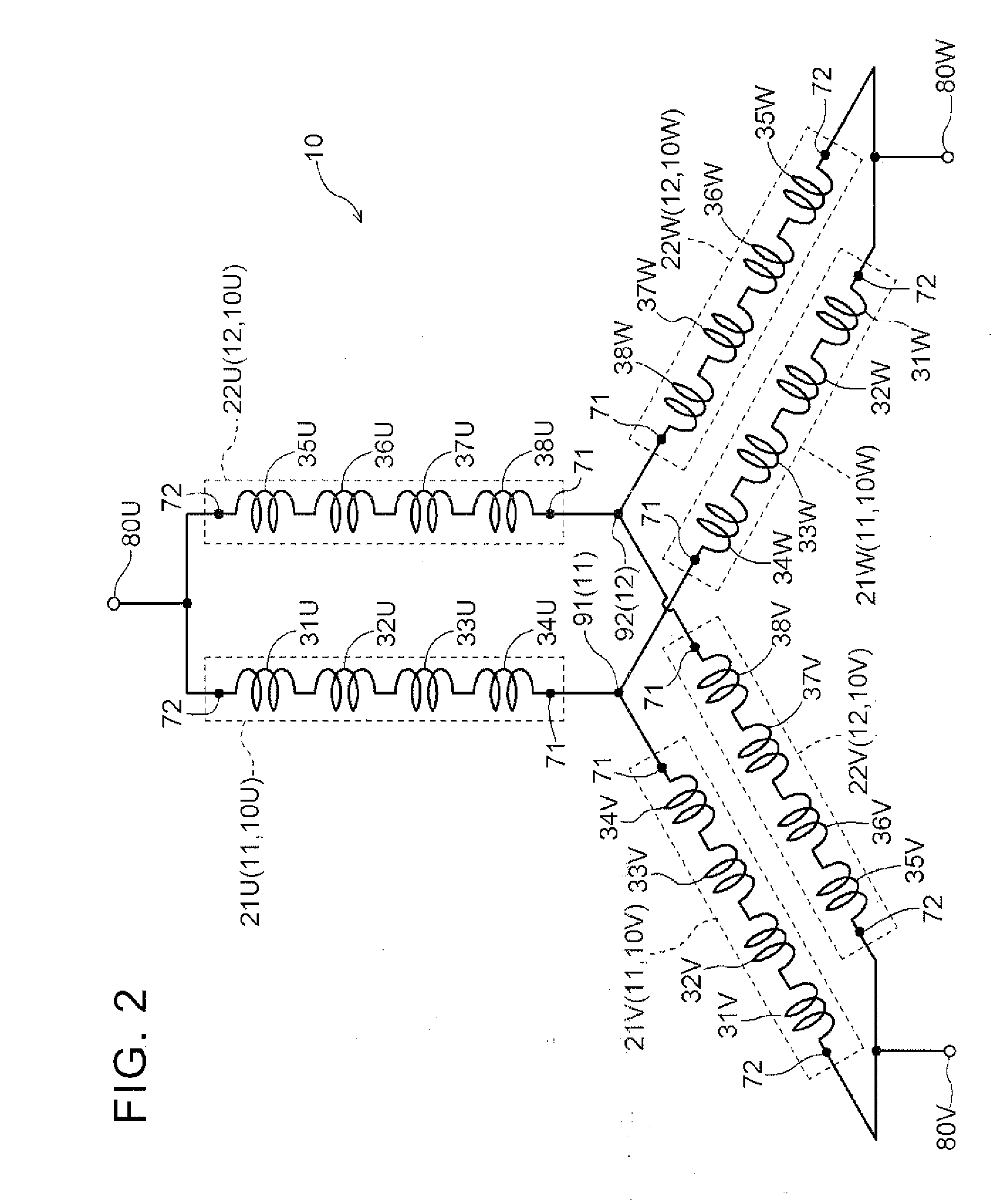
[0028]A first embodiment of a coil according to the present invention will be described with reference to the accompanying drawings. The coil according to the present invention will be described with respect to an example in which the coil is applied to a coil for rotating electrical machines, specifically an example in which the coil is applied to a coil 10 (see FIG. 1) that is wound around a stator core 2 of a stator 1. As shown in FIG. 1, the stator 1 according to the present embodiment is a stator for inner rotor type rotating electrical machines. As used herein, the term “rotating electrical machine” is used as a concept including all of a motor (electric motor), a generator (electric generator), and a motor-generator that functions both as a motor and as a generator as necessary. In the present embodiment, the stator core 2 corresponds to the “core” in the present invention.

[0029]In the following description, the “axial direction”, the “circumferential direc...

second embodiment

2. Second Embodiment

[0065]A second embodiment of the coil according to the present invention will be described with reference to FIGS. 11 and 12. The present embodiment is different from the first embodiment in that “N” is “4.” The differences from the first embodiment will be mainly described below, and the second embodiment is similar to the first embodiment unless otherwise specified.

[0066]As shown in FIG. 12, in the present embodiment, the coil 10 has four star connections, namely a first star connection 11, a second star connection 12, a third star connection 13, and a fourth star connection 14. Each of the four star connections 11 to 14 includes three phase coil portions corresponding to three phases, and first ends 71 of the three phase coil portions are connected together at a corresponding one of neutral points 91 to 94 that are formed independently for each of the star connections 11 to 14. In the present embodiment, each of the three phase coil portions included in each o...

third embodiment

3. Third Embodiment

[0072]A third embodiment of the coil according to the present invention will be described with reference to FIG. 13. Like FIG. 1, FIG. 13 shows only the turn portions of the unit coil portions, and does not show jumper portions and connection members that connect a coil end portion 10a and neutral points 91, 92. In the present embodiment, the shapes of U-phase unit coil portions 31U to 38U, V-phase unit coil portions 31V to 38V, and W-phase unit coil portions 31W to 38W (turn portions) as viewed in the axial direction L, and the overall arrangement and shape of the coil end portion 10a as viewed in the axial direction L are different from the first embodiment. In the first embodiment, as shown in FIG. 1, each unit coil portion (turn portion) has an arc shape along the circumferential direction C as viewed in the axial direction L. In the first embodiment, the unit coil portions of the three phases are designed to be arranged on concentric circles having different ...


PUM


Abstract

A coil that is wound around a core having a plurality of slots arranged so as to be distributed in a circumferential direction of a cylindrical core reference plane, and that has N (where N is an integer of 2 or more) star connections. Each of the N star connections includes three phase coil portions corresponding to respective three phases, and first ends of the three phase coil portions are connected together at a neutral point that is formed independently for each of the star connections, second ends of the N phase coil portions of the same phase which are included in the different star connections are connected to each other, a phase coil placement region where the phase coil portion is placed is designed to be continuous in the circumferential direction.

Description

TECHNICAL FIELD[0001]The present invention relates to coils that are wound around a core having a plurality of slots arranged so as to be distributed in a circumferential direction of a cylindrical core reference plane, and that have a plurality of star connections.BACKGROUND ART[0002]For example, there is a technique described in Japanese Patent Application Publication No. 2006-311733 (JP 2006-311733 A) (Patent Document 1) as related art of such coils as described above. Patent Document 1 discloses a coil having two star connections (Y-connections), in which a common neutral point having respective one ends of phase coil portions of each phase connected thereto is provided for the two star connections. In the configuration described in Patent Document 1, each of the two phase coil portions of the same phase which form a parallel circuit (series coil A and series coil B shown in FIG. 5 of Patent Document 1) is formed by two coil groups that are arranged so as to face each other in t...

Claims


Application Information

Patent Timeline
Patent Type & Authority Applications(United States)
IPC IPC(8): H02K3/28H02K3/12
CPCH02K3/12H02K3/28
Inventor NAKAGAWA, YOSHINARI
Owner AISIN AW CO LTD
Why Eureka
Try Eureka