
Two-channel monopulse radar for three-dimensional detection

a monopulse radar and two-channel technology, applied in the field of radar systems, can solve the problems of too large and too costly for practical implementation in automobile applications

Active Publication Date: 2015-03-05
AUTOLIV +1
View PDF11 Cites 7 Cited by
  • Summary
  • Abstract
  • Description
  • Claims
  • Application Information

AI Technical Summary

Benefits of technology

The present patent describes a two-channel monopulse radar system that can detect objects in three dimensions. The system includes a receiving antenna and two transmitting antennas that are spaced apart from each other. The first transmitting antenna is squinted in a first direction perpendicular to the focal plane axis and the second transmitting antenna is squinted in a second direction perpendicular to the focal plane axis. The technical effect of this design is that it allows for the more accurate detection of objects in three dimensions using a monopulse radar system.

Problems solved by technology

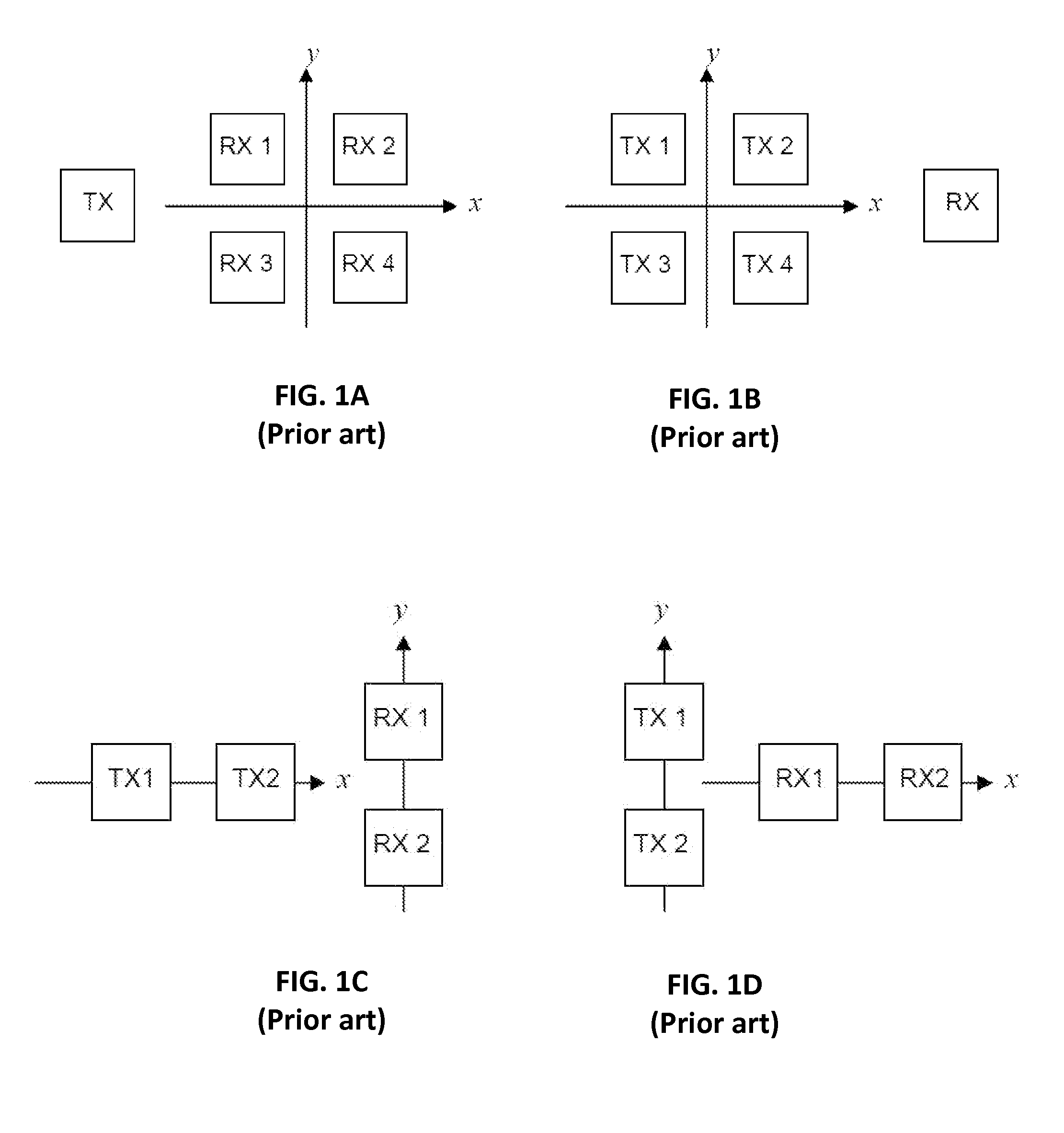
While four-channel monopulse radar systems are generally effective for determining the elevation and azimuth angles of target objects, the antenna and circuitry requirements of such systems can make them too large and too costly for practical implementation in automobile applications.

Method used


Image

  • Two-channel monopulse radar for three-dimensional detection
  • Two-channel monopulse radar for three-dimensional detection
  • Two-channel monopulse radar for three-dimensional detection

Examples


Embodiment Construction

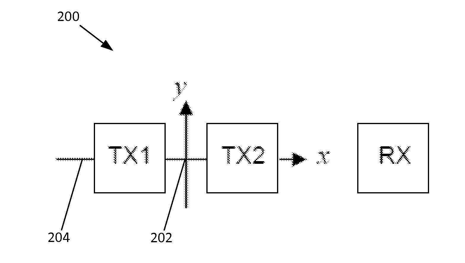
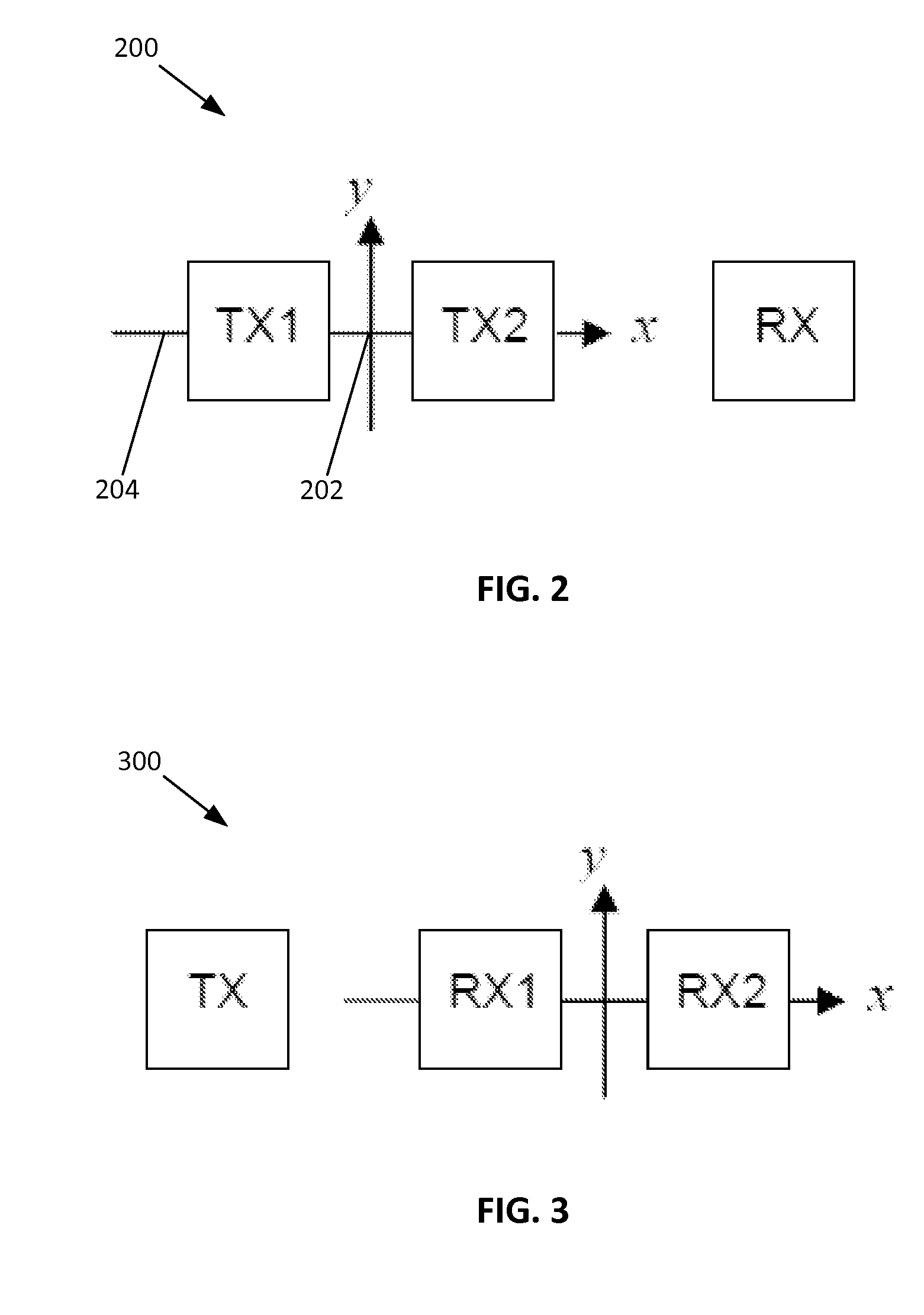
[0022]Referring to FIG. 2, a functional block diagram representation of a two-channel monopulse radar for three-dimensional detection 200 is shown. The radar 200 may generally include two transmitting antennas TX1 and TX2 and one common receiving antenna RX disposed in a substantially coplanar arrangement, such as on the surface of a dielectric substrate (not shown). The transmitting antennas TX1 and TX2 may be positioned on the focal plane of the radar 200 horizontally equidistant from the boresight axis 202 of the radar 200 along a focal plane axis 204 (the x axis in FIG. 2) that is perpendicular to the boresight axis 202. The transmitting antennas TX1 and TX2 may be spaced apart from one another a distance equal to about one half of one wavelength of the radar's center operating frequency. One of the transmitting antennas TX1 or TX2 may be vertically “squinted” at an angle of θ relative to the boresight axis 202, and the other transmitting antenna TX1 or TX2 may be vertically “sq...


PUM


Abstract

An apparatus for determining the position of a target object using a two-channel monopulse radar. The radar may include two transmitting antennas and one common receiving antenna disposed in a coplanar arrangement. The transmitting antennas may be positioned on the focal plane of the radar along a focal plane axis that extends through, and that is perpendicular with, a boresight axis of the radar. The transmitting antennas may be spaced apart from one another in a first dimension a distance equal to about one half of one wavelength of the radar's center operating frequency. One of the transmitting antennas may be squinted at an angle of θ1 relative to the boresight axis and the other transmitting antenna may be squinted at an angle of θ2 relative to the boresight axis in a second dimension. The transmitting antennas are not squinted relative to one another in the first dimension.

Description

FIELD OF THE DISCLOSURE[0001]The disclosure relates generally to the field of radar systems, and more particularly to monopulse radar systems for compact applications.BACKGROUND OF THE DISCLOSURE[0002]Over the past several decades, radar systems have been implemented in a broad range of applications for detecting target objects such as vehicles and airplanes. More recently, radar systems have been implemented in automobiles. Automotive radar systems have been developed for helping drivers to park their cars, to follow traffic at a safe distance, and to detect driving obstacles. For example, when an automotive radar system detects an obstacle or slowing traffic in front of the vehicle, the system may issue an audio and / or visual warning to the driver, such as in the form of an audible tone or a visible warning light. The system may also exercise active control over the vehicle, such as by applying the brakes, in order to avoid an accident.[0003]A radar system may detect the range (e....

Claims


Application Information

Patent Timeline
Patent Type & Authority Applications(United States)
IPC IPC(8): G01S13/00G01S7/28G01S13/931
CPCG01S7/28G01S13/003G01S13/4445G01S13/931H01Q1/28H01Q1/32H01Q21/0081H01Q21/065G01S13/4454G01S13/4463G01S13/40G01S13/53G01S13/56
Inventor DING, XUERUSCHAEFER, JEFFMARPLE, MATTHEW
Owner AUTOLIV
Learn More