Three-dimensional image display apparatus

a display device and three-dimensional technology, applied in the field of display devices, can solve the problems of uneven distribution of light, affecting the entire display effect, and the peripheral of the electrodes may not be completely rotated, so as to reduce the moiré issue of optical interference, improve the display effect, and avoid color shift

Active Publication Date: 2015-03-05
INNOLUX CORP +1
View PDF2 Cites 7 Cited by
  • Summary
  • Abstract
  • Description
  • Claims
  • Application Information

AI Technical Summary

Benefits of technology

[0014]As mentioned above, in the 3D image display apparatus of the disclosure, the first portion has a first curvature radius and the second portion has a second curvature radius, and the first curvature radius is different from the second curvature radius. Otherwise, the first portion is asymmetric to an axis that is orthogonal to the display panel and the second portion is also asymmetric to the axis. Accordingly, this invention can reduce the moiré issue of optical interference and avoid the color shift, thereby improving the display effect.

Problems solved by technology

When operating under the portrait mode, even if an opening ratio of the parallax barrier is optimized to reduce the moiré and color shift issue, the liquid crystal cells in the proximity of the peripheral of the electrodes may not be rotated completely or the distribution thereof may be uneven.
Accordingly, the users may suffer from the color shift and moiré issues due to the difference of the viewing angles, thereby affecting the entire displaying effect.

Method used


Image

  • Three-dimensional image display apparatus
  • Three-dimensional image display apparatus
  • Three-dimensional image display apparatus

Examples


Embodiment Construction

[0032]The embodiments of the invention will be apparent from the following detailed description, which proceeds with reference to the accompanying drawings, wherein the same references relate to the same elements.

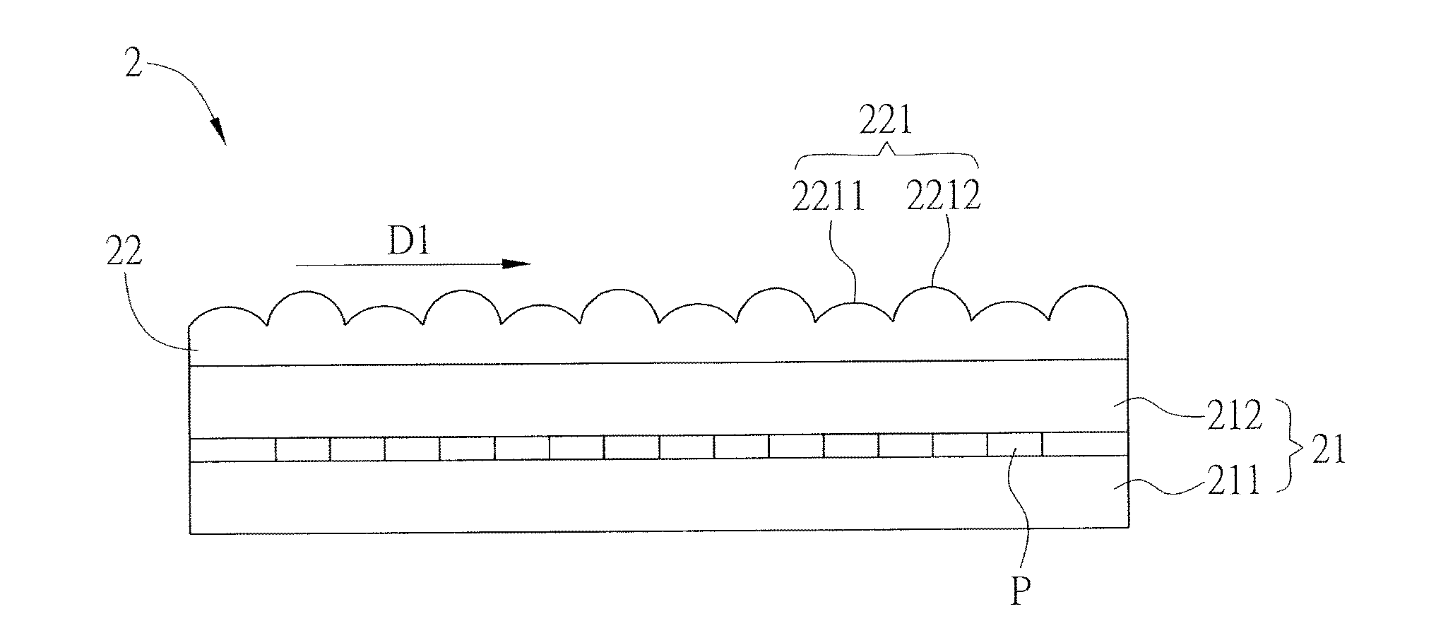
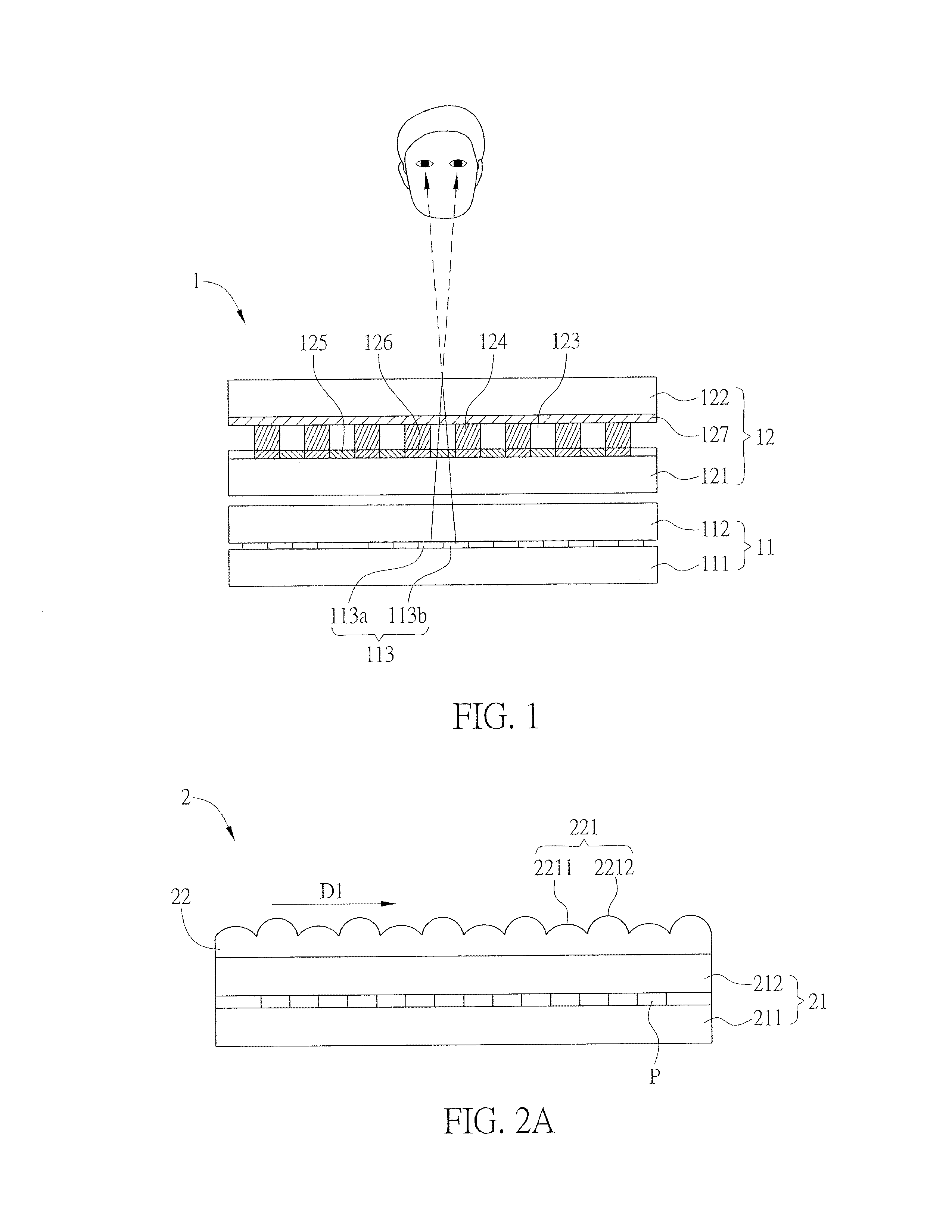
[0033]FIGS. 2A to 2C are schematic diagrams showing a three-dimensional (3D) image display apparatus 2 according to a preferred embodiment of the disclosure. The 3D image display apparatus 2 includes a display panel 21 and a 3D image optical structure 22. In practice, the display panel 21 can be any device for displaying two-dimensional image such as a LCD panel, an electroluminescent display panel, or an electrophoretic display panel.

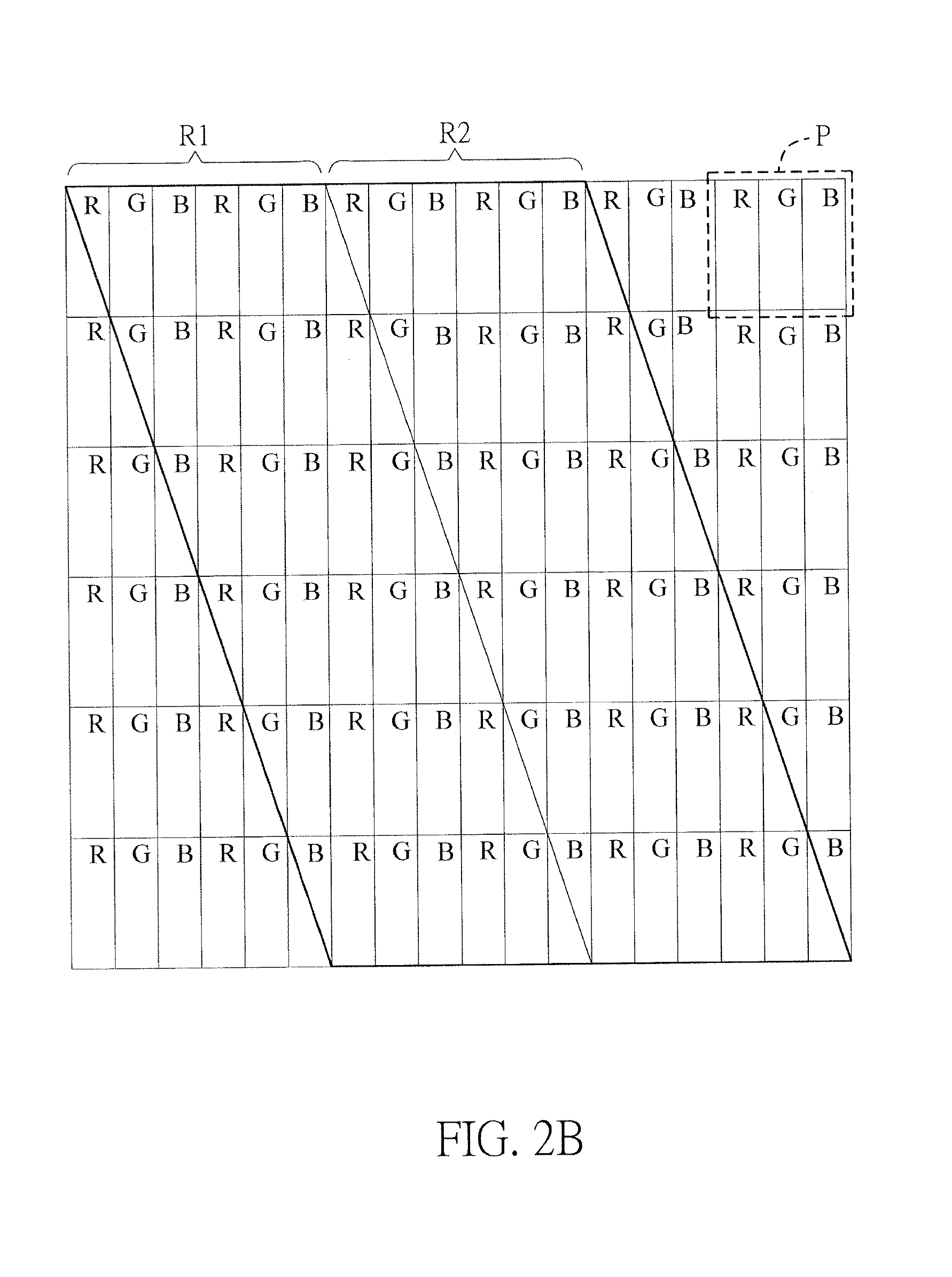
[0034]In this embodiment, the display panel 21 is a LCD panel, which has two opposite substrates 211 and 212, and a plurality of pixels P. The pixels P are disposed between the substrates 211 and 212, and arranged in an array. Each pixel P includes three sub-pixels R, G and B, and the pixels P sequentially provide the left-eye image and the ri...


PUM


Abstract

A three-dimensional (3D) image display apparatus includes a display panel and a 3D image optical structure. The display panel has pixels arranged in an array and the pixels have a first region and a second region disposed adjacent to each other. The 3D image optical structure includes a plurality of first optical units disposed along a first direction. Each first optical unit has at least one first portion corresponding to the first region and at least one second portion corresponding to the second region. The first portion has a first curvature radius and a plurality of corresponding first circle centers, and the second portion has a second curvature radius and a plurality of corresponding second circle centers. The first curvature radius is different from the second curvature radius, and the first circle centers are not overlapped with the second circle centers in the vertical projection direction.

Description

CROSS REFERENCE TO RELATED APPLICATIONS[0001]This application is a Continuation-In-Part (CIP) of an earlier filed, pending, application, having application Ser. No. 13 / 602,014 and filed on Aug. 31, 2012, the content of which, including drawings, is expressly incorporated by reference herein.BACKGROUND[0002]1. Technical Field[0003]The present disclosure relates to a display apparatus and, in particular, to a three-dimensional (3D) image display device.[0004]2. Related Art[0005]In general, three-dimensional (3D) image display apparatuses are categorized into stereoscopic display apparatuses and autostereoscopic display apparatuses (also referred to naked-eye type 3D image display apparatuses). Regarding to the stereoscopic display apparatus, the user has to wear a viewing aid, such as shutter glasses, so that the left and right eyes of the user can receive different images respectively, and thereby perceiving a 3D image. Regarding to the autostereoscopic display apparatus, a specially...

Claims


Application Information

Patent Timeline
Patent Type & Authority Applications(United States)
IPC IPC(8): G02B27/22G02B30/29
CPCG02B27/2214G02B3/12G02B3/0043G02B3/005G02B3/14H04N13/305G02B30/29G02B30/27
Inventor SUMI, NAOKIARAKI, TOSHIHIKO
Owner INNOLUX CORP
Why Eureka
Try Eureka