Method for controlling tunable wavelength laser

Active Publication Date: 2015-03-05
SUMITOMO ELECTRIC DEVICE INNOVATIONS
View PDF11 Cites 5 Cited by
  • Summary
  • Abstract
  • Description
  • Claims
  • Application Information

AI Technical Summary

Benefits of technology

The technology described in this patent allows for the control of a tunable wavelength laser through the use of stored control conditions. These control conditions are specific to the ITU-T grid wavelengths, meaning that the laser can only be controlled to oscillate at those specific wavelengths. However, this invention provides a method to control the laser so that it can oscillate at any wavelength, which can save time during startup.

Problems solved by technology

For this reason, it is impossible to perform a control so that oscillation occurs at any wavelength other than the grid wavelengths.
However, obtaining setting values at each calculation lengthens the time necessary for start-up.

Method used


Image

  • Method for controlling tunable wavelength laser
  • Method for controlling tunable wavelength laser
  • Method for controlling tunable wavelength laser

Examples


first embodiment

[0023]Hereinafter, embodiments of the present invention will be described with reference to the accompanying drawings.

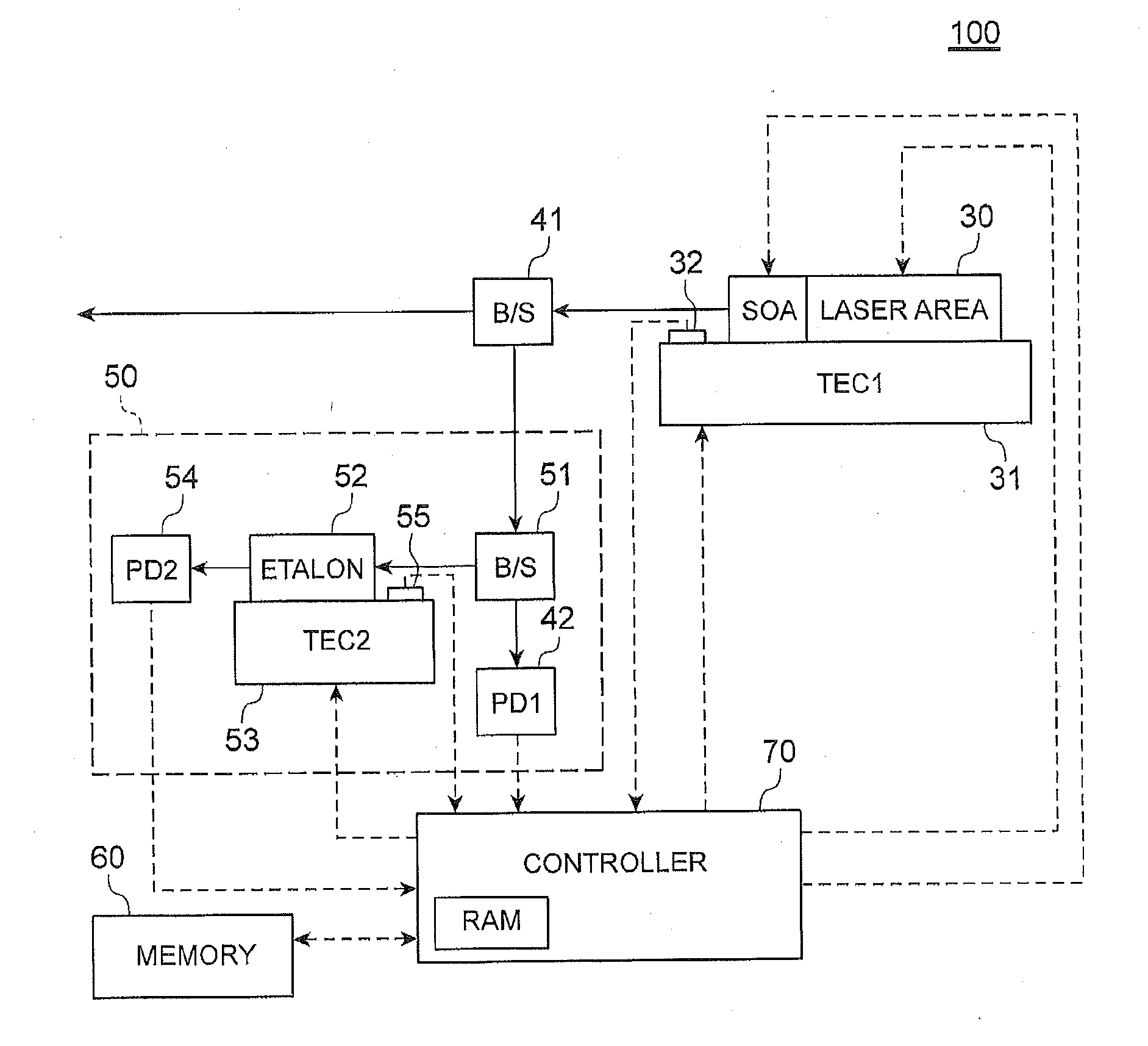
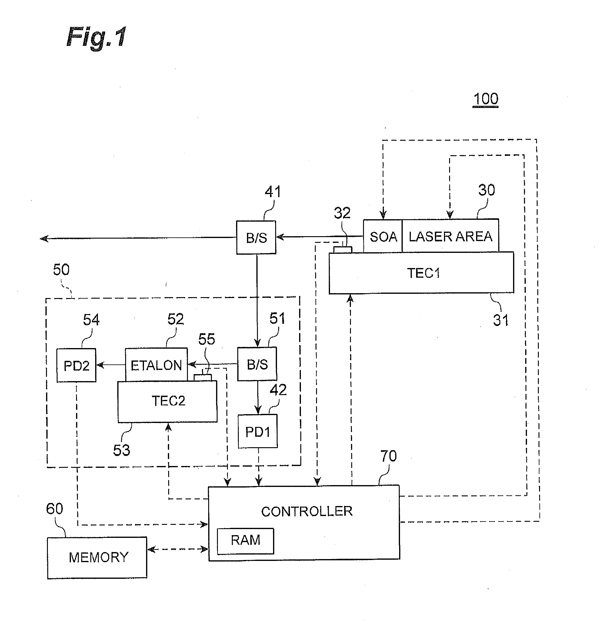
[0024]FIG. 1 is a block diagram illustrating an overall configuration of a tunable wavelength laser 100 according to a first embodiment. As illustrated in FIG. 1, the tunable wavelength laser 100 includes a semiconductor laser 30, the wavelength of which can be controlled (tunable semiconductor laser), as a laser device. The semiconductor laser 30 according to the present embodiment is provided with an area, which is connected to a laser area and becomes a SOA (Semiconductor Optical Amplifier). The SOA functions as an optical output control unit. The SOA can increase / decrease the intensity of optical output as desired. The SOA can also control the intensity of optical output to be substantially zero. The tunable wavelength laser 100 includes a sensing unit 50, a memory 60, a controller 70, and the like. The sensing unit 50 functions as an output sensing unit and a wa...

second embodiment

[0069]In the case of the tunable wavelength laser 100 according to the first embodiment, the required wavelength setting value of FIG. 6 is written in the memory 60 when the required wavelength is implemented, but the present invention is not limited thereto. For example, a correction amount ΔT may be associated with the corresponding required wavelength and written in the memory 60. The correction amount ΔT is an amount of correction of the temperature value of the semiconductor laser 30 when the required wavelength is implemented under stable AFC control. In addition, the correction amount ΔT is a value satisfying TLD=TLD′+ΔT when a temperature value TLD under stable AFC control is TLD, and the temperature value TLD of the update setting value is TLD′. FIG. 11 is a diagram illustrating the correction amount ΔT written in the memory 60.

[0070]The controller 70 according to the present embodiment calculates the update setting value based on the wavelength difference ΔF. Next, the con...


PUM


Abstract

A driving condition for causing the tunable wavelength laser to conduct laser oscillation at a first wavelength is acquired. a driving condition for causing the tunable wavelength laser to conduct laser oscillation at the second wavelength is calculated. The tunable wavelength laser is driven based on the driving condition of the second wavelength, feedback control that changes the driving condition of the tunable wavelength laser based on a difference between an output of the wavelength sensing unit and the target value is performed, and the tunable wavelength laser is caused to oscillate at the second wavelength. The driving condition of the tunable wavelength laser obtained by the feedback control when oscillation has occurred at the second wavelength is stored in the memory. Thereafter, the tunable wavelength laser is driven with reference to the stored driving condition of the tunable wavelength laser.

Description

FIELD OF THE INVENTION[0001]The present invention relates to a method for controlling a tunable wavelength laser.BACKGROUND OF THE INVENTION[0002]A tunable wavelength laser having a selectable output wavelength is disclosed in Laid-open Japanese Patent Publication No. 2009-026996, for example.SUMMARY OF THE INVENTION[0003]According to the technology of Patent Literature (Laid-open Japanese Patent Publication No. 2009-026996), control conditions for obtaining grid wavelengths determined by ITU-T (International Telecommunication Union Telecommunication Standardization Sector) (hereinafter, simply referred to as grid wavelengths) are stored in a memory. A control is conducted so that oscillation occurs at any wavelength of the grid wavelengths based on the stored control conditions. For this reason, it is impossible to perform a control so that oscillation occurs at any wavelength other than the grid wavelengths. In this regard, it is considered to cause oscillation at a wavelength oth...

Claims


Application Information

Patent Timeline
IPC IPC(8): H01S5/026H01S3/10
CPCH01S3/1003H01S5/026H01S5/0687H01S5/0265H01S5/0617H01S5/06256H01S5/06258H01S5/1209H01S5/1212
Inventor TANAKA, HIROKAZUSHIBATA, MASAOMIYATA, MITSUYOSHI
Owner SUMITOMO ELECTRIC DEVICE INNOVATIONS
Why Eureka
Try Eureka