
Clock synchronizer for aligning remote devices

a remote device and clock synchronizer technology, applied in the field of wireless power and data applications, can solve the problems of not meeting, picc can lose synchronization with the pcd field, and the plm may not be strong enough for the pcd,

Active Publication Date: 2015-03-05
NXP BV
View PDF16 Cites 27 Cited by
  • Summary
  • Abstract
  • Description
  • Claims
  • Application Information

AI Technical Summary

Benefits of technology

This patent is about improving NFC communication devices and solving problems with them. The technical effects of the patent include resolving issues with NFC communication and providing better functionality.

Problems solved by technology

In instances where the PICC-side antenna is small, PLM may not be strong enough for the PCD to receive communications, and / or may not meet International Organization for Standardization (ISO) requirements.
While transmitting, the PICC can lose synchronization with the PCD field because the active modulation signal overwrites the PICC.
While wireless communications as discussed above have been useful, effecting such communication in an efficient, secure and reliable manner can be challenging.
For example, data communications may be lost when a distance between devices is too great, or when communicated data becomes corrupt.
These and other matters have presented challenges to different types of communications, for a variety of applications.

Method used


Image

  • Clock synchronizer for aligning remote devices
  • Clock synchronizer for aligning remote devices
  • Clock synchronizer for aligning remote devices

Examples


Embodiment Construction

[0015]While the invention is amenable to various modifications and alternative forms, specifics thereof have been shown by way of example in the drawings and will be described in detail. It should be understood, however, that the intention is not to limit the invention to the particular embodiments described. On the contrary, the intention is to cover all modifications, equivalents, and alternatives falling within the scope of the invention, including aspects defined in the claims. In addition, the term “example” as used throughout this application is only by way of illustration, and not limitation.

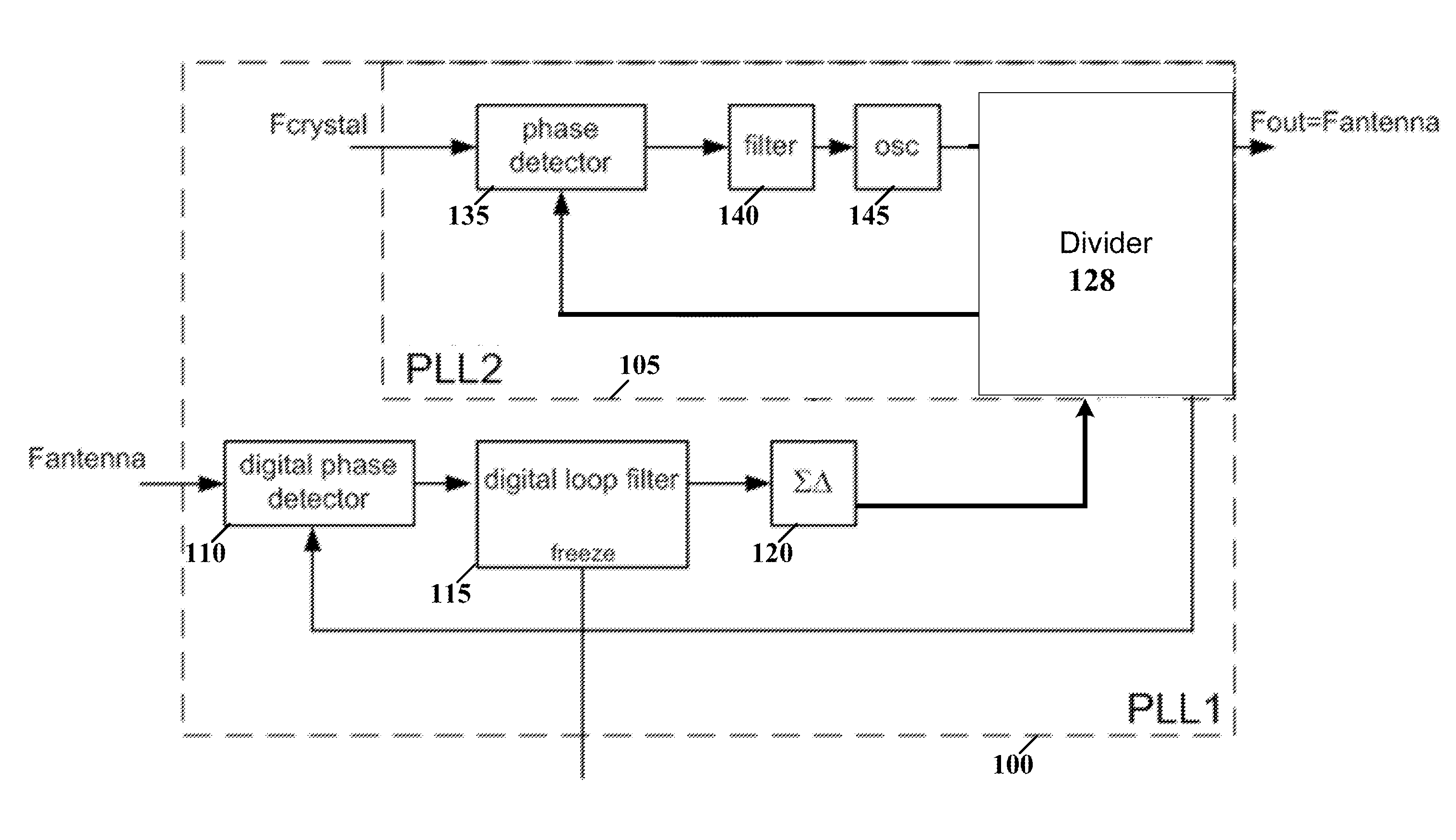
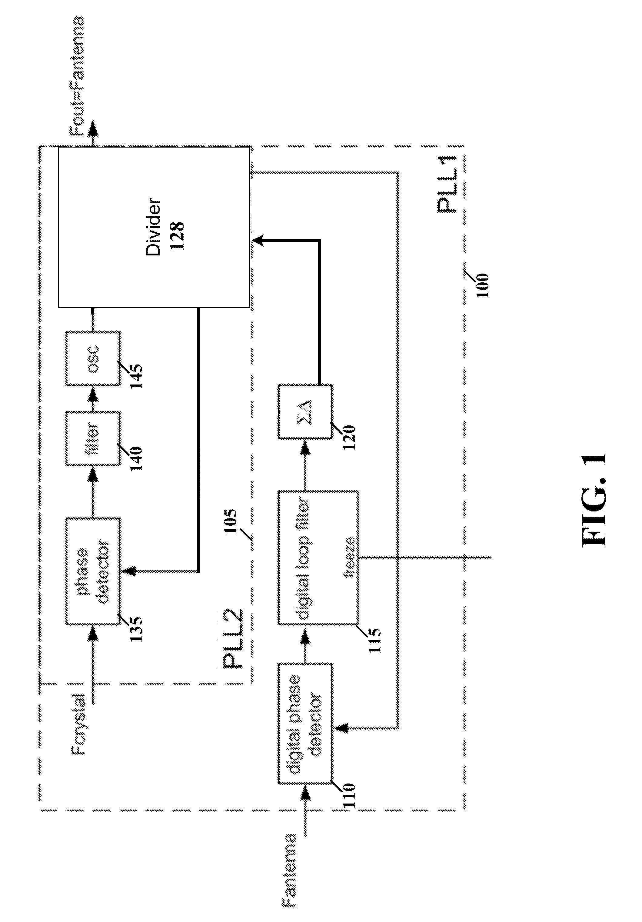
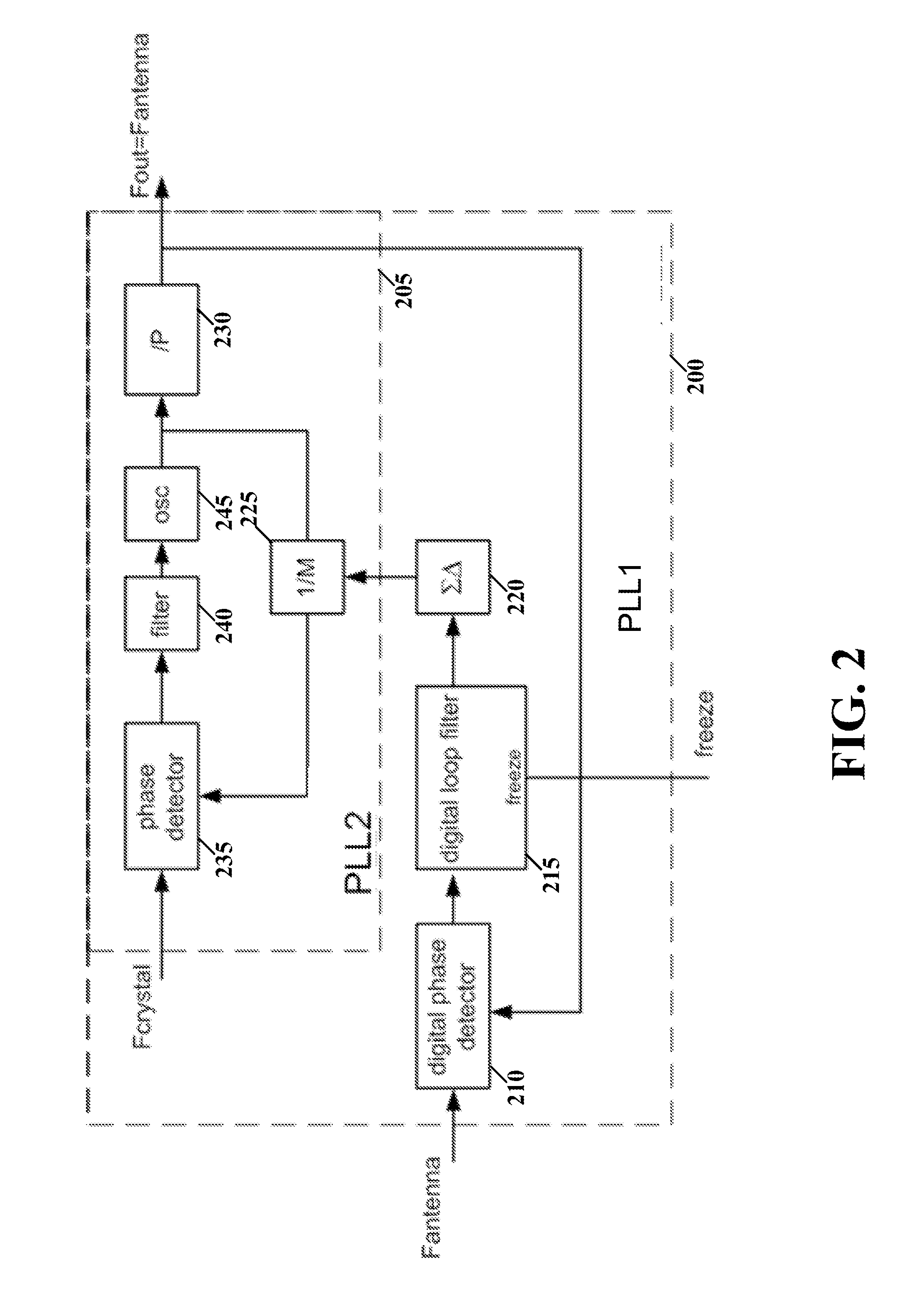
[0016]Aspects of the present invention are believed to be applicable to a variety of different types of devices, systems and arrangements for involving a clock synchronizer for aligning remote devices using near field communication. For instance, various aspects of the present disclosure include synchronized communication between a PCD and a PICC during an active load modulation process. ...


PUM


Abstract

Various aspects of the present disclosure are directed apparatuses and methods including a first phase locked loop (PLL) circuit and a second PLL circuit. The first PLL circuit receives a carrier signal that is transmitted over a communications channel from a non-synchronous device, and generates a PLL-PLL control signal. The second PLL circuit receives a stable reference-oscillation signal, and, in response to the PLL-PLL control signal indicating a frequency offset, adjusts a fractional divider ratio of the second PLL circuit. The first PLL circuit and the second PLL circuit are configured to produce an output frequency signal that is synchronous to the carrier signal.

Description

FIELD OF THE INVENTION[0001]Aspects of various embodiments of the present invention are directed to wireless power and data applications.BACKGROUND OF THE INVENTION[0002]Wireless communications have seen increasing use in a variety of fields and devices. For instance, identification products such as smart cards and RIFD (Radio Frequency Identification) tags are used widely in fields such as transport (e.g., ticketing, road tolling, baggage tagging), finance (e.g., debit and credit cards, electronic purses, merchant cards), communications (e.g., SIM cards for GSM (Global System for Mobile Communications) phones), and tracking (e.g., access control, inventory management, asset tracking) Many such applications involve products compliant with international standard ISO14443A identification cards, and provide RF (Radio Frequency) communication technology for transmitting data between a card or tag and a reader device. For example, in electronic ticketing for public transport, travelers c...

Claims


Application Information

Patent Timeline
IPC IPC(8): H04L7/033H04L7/00
CPCH04L7/0079H04L7/0331H03L7/0992H03L7/14H03L7/23H03L7/235H03L7/087
Inventor VERLINDEN, JOSVAN DE BEEK, REMCO CORNELIS HERMAN
Owner NXP BV
Learn More